

Abstract – Plasma antennas are used for transmission and reception. They have capabilities of getting data over a wide frequency range (500MHz – 20GHz). The plasma antenna reverts to a dielectric tube that has a small radar cross-section, rendering it essentially invisible to radar and free from electromagnetic scattering. The plasma antenna can be configured that a high – frequency, electric – warfare signed can pass through the antenna without appreciable interaction, as long as receiving signals at a lower frequency. Data testing and measurement can be inspected efficiently by using plasma antennas. The plasma antenna technology relies on plasma elements rather than a traditional metallic wires or elements. The feasibility of a plasma antenna is provided by plasma conductivity, that is given by free electrons obtained by gas ionization with the application of an intense electro – magnetic field. The fundamental base of plasma antenna is the use of an ionized medium as a conductor. Plasma can be defined as a set of quasi – neutral particles with free electric charge carrier which behave collectively.
- Plasma antenna structure and functionality
Plasma antenna is a type of RF antenna in which plasma is used instead of the metal elements of a traditional antenna. A plasma antenna can be used for both transmission and reception. Plasma antennas are used partially or fully ionized gas as the conducting medium instead of metal to create an antenna. The advantages of plasma antennas are that they are highly reconfigurable and can be turned on and off. It is a target to reduce the power required to ionize the gas at various plasma densities and this has been achieved by various techniques including pulsing techniques. The power requirements for plasma antenna operation continue to decrease. The same geometric resonances apply to plasma antennas as metal antennas. Plasma antennas of the same shape, length, and frequency of corresponding metal antennas have the same radiation patterns. Plasma antennas have the advantage of re-configurability. One configurable plasma antenna is structures with long plasma column which is excited by surface wave, which acts as a plasma antenna. By changing the operation parameters of plasma antenna (pressure, drive frequency, input power, radius of glass tube, length of plasma column, and argon gas), a single plasma antenna (plasma column) can be transformed to multiple small antenna elements (plasma blobs). Operating parameters control the number, length, and separation between two antenna elements. The entire structure of antenna elements can be treated as a phased array broadside vertical plasma antenna, which produces more directive radiation pattern than the single plasma antenna as well as physical properties and directivity of the antenna can be controlled by operating parameters. The advantages of a plasma antenna over the conventional antenna are in the sense that different antennas can be formed by tuning the operating parameters. Plasma can be generated by electron impact ionization, photo ionization, or simply heating the gas. The region outside the sheath is called the positive column, where uniform plasma exists. The characteristics of the electromagnetic wave propagating in the plasma are closely related to the plasma’s relative permittivity ξ, which can be expressed  and
and
 .
.
Where ε∞, the relative dielectric constant at infinite frequency and ![]() is collision frequency. The plasma frequency equation is shown in
is collision frequency. The plasma frequency equation is shown in  .Ν is the plasma density,
 ![]() is the electric charge, m is the mass of an electron and ƒρ is the inherent plasma frequency.
is the electric charge, m is the mass of an electron and ƒρ is the inherent plasma frequency.
Eq.  represents the plasma conductivity equation.
![]()
![]()
A “plasma dielectric tube” can be described as a system where a dielectric material, usually in a tubular form, contains or is surrounded by a plasma. This configuration can be used to create electrically reconfigurable waveguides for advanced communication systems, where the plasma’s density and the dielectric’s properties alter wave propagation (Fig. 1).
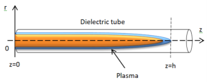
Fig. 1 Plasma dielectric tube (plasma column).
A “plasma antenna excited by the surfaguide” is a type of gaseous plasma antenna where a surfaguide structure is used to generate and sustain a conductive plasma column using microwave power. The surfaguide acts as a surface wave launcher to create a plasma column within an isolated tube, which then functions as a reconfigurable, high-efficiency antenna that can transmit and receive electromagnetic signals (Fig. 2).
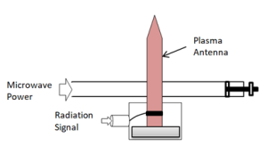
Fig. 2 An arrangement of the plasma antenna excited by the surfaguide.
The surfatron is a plasma source. It consists of a microwave cavity (Surfatron, around a plasma-quartz tube). The Surfatron possess an inner slit that allows the coupling of electromagnetic energy to the plasma via surface waves. The surface waves propagate along the quartz tube allowing the creation of plasma further away from the surfatron and, at the same time, the propagation of the surface wave in self-consistent manner. The plasma column ends when there is not enough power to sustain it. The principle behind the fluid plasma model is to have electrons, ionized and excited species, by a massless charged fluid with the specifications provided. Since plasma is weakly ionized, the model should take the neural gas specifications into account. By modelling the plasma column (using fluid models), we recognize two typical models, Plasma model and Electromagnetic field model.
- Plasma antenna’s surfatron waveguide equivalent circuit
The Surfatron waveguide equivalent circuit is corresponded to the approximate electric field distribution in the region adjacent to the reference plane. The equivalent circuit represents the phenomena occurring within the plasma source. The circuit elements are related to electromagnetic energy stored or dissipated in the system. A power balance is achievable and the response characteristics of the plasma source is obtained by using the methods of circuit analysis rather than solving full set of electromagnetic field equations. By placing a simple model of the plasma source, we can determine when the diameter of the outer conductor of the coaxial section is small compared with the width of the waveguide. All the impedances in the equivalent circuit are related to a single reference plane coincident with the axis of the coaxial section. The equivalent circuit is corresponded to the approximate electric field distribution in the region adjacent to the reference plane (Fig. 3).
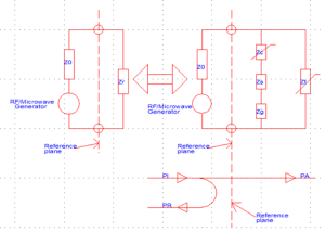
Fig. 3 Surfatron waveguide equivalent circuit is corresponded to the approximate electric field distribution in the
region adjacent to the reference plane.
The wave power in the microwave circuit represents the wave guide surfatron, there are PI, incident power, PR, reflected power, and PA, absorbed power. Zg represents the impedance of the gap loaded with the plasma and it includes the effect of the power carried away by the surface waves launched from the gap region along the discharge tube in both directions. The impedance Zs represents the influence of the sleeve in the waveguide. The sleeve contributes an additional resonant mode and the design is capable to cover whole waveguide band. The waveguide connector is configured to receive a waveguide in a first orientation or a second orientation at the first end, the second orientation is rotation of the waveguide from the first orientation by either 45° or 90° to change polarizations. The waveguide connector assembly includes a movable sleeve having a first end, a second end, a body, and an engaging surface. Zt and Zc are input impedances of the waveguide and coaxial sections.
Reference
- Aluf, Advanced Microwave RF Antennas and Circuits, Nonlinearity Applications in Engineering, Springer, Edition 2, 2025, In two Volumes, ISBN: 978-3-031-58699-6, EAN: 9783031586996.
https://link.springer.com/book/9783031586996
