

Abstract
Real-time deterministic Ethernet protocols, such as EtherCAT, have enabled synchronized operation of multiaxis motion control systems.1 There are two aspects to this synchronization. First, the delivery of command and references between the various control nodes must be synchronized to a common clock and, second, the execution of the control algorithms and feedback functions must be synchronized to the same clock. The first kind of synchronization is well understood and an inherent part of the network controller. However, the second kind of synchronization has up to this point been neglected and is now a bottleneck when it comes to motion control performance.
This article presents novel concepts to synchronize motor drives all the way from a network controller and down the motor terminals and sensors. The presented technologies enable much improved synchronization that leads to significantly increased control performance.
Problem Statement and State of the Art
To define the limitations of state-of-the-art solutions, consider a 2-axis networked motion control system, as shown in Figure 1. A motion control master is sending commands and references across a real-time network to two servo controllers, with each servo controller constituting a slave node on the network. The servo controller itself consists of a network controller, a motor controller, a power inverter, and a motor/encoder.

Figure 1. A typical 2-axis network motion control system.
The real-time network protocols employ different methods to synchronize slave nodes to the master, but an often used approach is to have a local synchronized clock at each node. This common understanding of time ensures references and commands for all servo axes are tightly synchronized. In other words, all network controllers on the real-time network are synchronized.
Typically, there are two interrupt lines between the network controller and the motor controller. The first notifies the motor controller when it is time to gather inputs and put them on the network. The second notifies the motor controller when to read data from the network. Following this approach, the data exchange between the motion controller and the motor controller happens in a synchronized manner and very high timing accuracy is possible. However, it is not enough to get synchronized data across to the motor controllers; the motor controllers must also be able to respond to the data in a synchronized way. Without this capability, the motor controllers cannot take advantage of the timing accuracy of the network. When it comes to responding to references and commands, the motor controller’s I/Os pose a problem.
Each of the I/Os in a motor controller, such as pulse-width modulation (PWM) timers and ADCs, have an inherent delay and time quantization. As an example, consider the PWM timer generating gate drive signals for the power inverter, as shown in Figure 2. The timer generates gate signals by comparing reference Mx to an up-down counter. When Mx is changed by the control algorithm, the new duty cycle does not take effect until the next PWM period. This is equivalent to a zero-order hold effect meaning the duty cycle is only updated once per PWM period, T, or twice if double update mode is used.
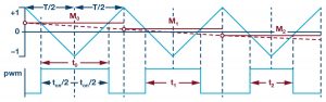
Figure 2. Update of duty cycle for PWM timer.
No matter how tightly the data exchange is synchronized on the real-time network, the time quantization of the PWM timer ends up being the determining factor in axis synchronization. When a new reference is received, it is not possible to respond to it until a new duty cycle takes effect. This introduces a time uncertainty of up to one PWM period, which is typically in the range of 50 μs to 100 μs. In effect, there will be an undefined and varying phase relationship between the network synchronization period and the PWM period. Compare this to a time uncertainty of sub-1 μs on the real-time network and it is clear that the I/Os of the motor controller play a crucial role when it comes to synchronizing motion control over a network. In fact, it is not the real-time network that determines the synchronization accuracy—rather it is the I/Os of the system.
Again referring to Figure 1, the system has three synchronization domains, A, B, and C, that are not tied together. They are effectively out of synchronization with a variable uncertainty of up to one PWM period.
Synchronization Uncertainty and Application Impact
The impact of timing uncertainty can be clearly seen in high performance multiaxis servo systems for applications like robotics and machining. The varying time offset between motor control axes at the I/O level has a direct and measurable impact on the final three-dimensional positioning accuracy of the robot or machine tool.
Consider a simple motion profile, as shown in Figure 3. In this example, the motor speed reference (red curve) is ramped up and then back down again. If the ramp rate is within the capability of the electromechanical system, the actual speed is expected to follow the reference. However, if there is a delay anywhere in the system, the actual speed (blue curve) will lag reference, which results is a position error, Δθ.
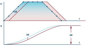
Figure 3. Effect of timing delay on position accuracy.
In multiaxis machines, a target position (x, y, z) is translated into angular axis profiles (θ1, …, θn) according to the mechanical construction of the machine. The angular axis profiles define a sequence of equally time spaced position/velocity commands for each axis. Any difference in timing between the axes results in reduced accuracy of the machine. Consider the 2-axis example shown in Figure 4. A target path for the machine is described by a set of (x, y) coordinates. A delay causes a timing error on the command for the y-axis and the actual path ends up being irregular.
The impact of a constant delay may, in some cases, be minimized by proper compensation. More critical is a varying and unknown delay for which compensation is impossible. Furthermore, a varying delay results in varying control loop gain, which makes it difficult to tune the loop for optimal performance.
It should be noted that a delay anywhere in the system will cause inaccuracy in the precision of the machine. As a consequence, minimizing or eliminating delays enables increased productivity and end-product quality.
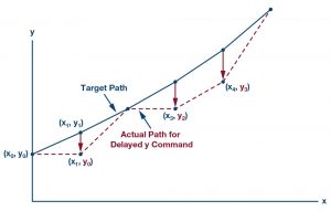
Figure 4. Effect of timing delay on position accuracy.
Synchronization and New Control Topologies
The traditional approach to motion control is shown in the top part of Figure 5. A motion controller, typically a PLC, sends position references (θ*) to a motor controller over a real-time network. The motor controller consists of three cascaded feedback loops with the inner loop controlling torque/current (T/i), the middle loop controlling speed (ω), and the other loop controlling position (θ). The torque loop has the highest bandwidth and the position loop has the lowest. Feedback from the plant is kept local to the motor controller and is tightly synchronized with the control algorithm and pulse-width modulator.

Figure 5. Traditional (top) and emerging (bottom) motion control topologies.
With this system topology, axes are synchronized through the exchange of position references between the motion and motor controllers, but the correlation to synchronization of the motor controller’s I/O (feedback and PWM) only becomes an issue for very high precision applications such as CNC machining. The position loop often has fairly low bandwidth and is therefore less sensitive to synchronization of I/O. That means synchronization of nodes at a reference level typically gives acceptable performance even though the network and I/O are in different synchronization domains.
While the control topology shown at the top of Figure 5 is common, other control partitioning approaches are also used in which position and/or speed loops are implemented at the motion controller side, and speed/torque references are passed across the network. Recent trends in the industry are indicating a move toward a new partitioning method, in which all of the control loops are moved away from the motor controllers to a powerful motion controller on the master side of the network (see the bottom of Figure 5). The data exchange on the real-time-network is a voltage reference (v*) for the motor controller and plant feedback (i, ω, θ) for the motion controller. This control topology, which is enabled by powerful multicore PLCs and real-time networks, has several benefits. Firstly, the architecture is very scalable. Axes can also be easily added/removed without having to worry about the processing power of the motor controller. Secondly, increased precision is possible since both trajectory planning and motion control are done in one central place.
The new control topology has drawbacks, too. By removing the control algorithms from the motor controller, tight synchronization of code execution and I/O is lost. The higher the bandwidth of a control loop, the more of a problem the loss of I/O synchronization is. The torque/current loop is especially sensitive to synchronization.
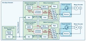
Figure 6. An I/O scheduler ties the sync domains together.
Proposed Solution
Moving the faster control loops to the motion controller creates a demand for synchronization all the way from the network master and down to the motor terminals.
The overall idea is to bring the I/Os of all axes into synchronization with the network so that everything runs in one sync domain. Figure 6 shows an I/O event scheduler, which sits between the network controller and the motor controller. The main function of the I/O event scheduler is to generate sync/reset pulses to all the peripherals so that they are kept in synchronism with the network traffic. The I/O event scheduler takes the frame sync signal, which is derived from the local clock of the network controller, and outputs appropriate hardware triggers for all I/Os that must be kept synchronized to the network.
Each I/O has its own set of timing/reset requirements, which means the I/O event scheduler must provide tailored triggers for each I/O. While trigger requirements differ, a general principle applies to all of them. Firstly, all triggers must be referenced to the frame sync. Secondly, there is a delay/offset associated with each trigger. This delay is related to the I/O’s inherent delay—for example, the conversion time of an ADC or the group delay of a sinc filter. Thirdly, there is the response time of the I/O—for example, the transfer of data from an ADC. The I/O event scheduler knows the timing requirements of each I/O and adjusts the trigger/reset pulses to the local clock continuously. The principle behind generating each output pulse of the I/O event scheduler is summarized in Figure
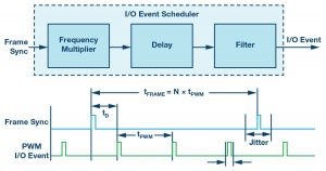
Figure 7. The I/O scheduler generates trigger pulses.
In most networked motion control systems, the frame rate, and hence the frame sync rate, is equal to or lower than the PWM update rate of the motor controller. This means that the I/O event scheduler must provide at least one and possibly several trigger pulses per frame period. For example, if the frame rate is 10 kHz and the PWM rate is 10 kHz, the I/O event scheduler must provide 1 trigger pulse per network frame and, similarly, if the frame rate is 1 kHz and the PWM rate is 10 kHz, the I/O event scheduler must provide 10 trigger pulses per network frame. This is equivalent to the frequency multiplier in Figure 7. A delay, tD, is applied to each synchronization pulse to compensate for the inherent delay of each I/O. The final element of the I/O event scheduler is an intelligent filtering function. On every network there is some jitter on the traffic. The filter reduces the jitter on trigger pulses and also ensures the rate of change of frame sync frequency is limited.
The bottom half of Figure 7 shows an example timing diagram for PWM synchronization. Note in this example how the frame sync frequency is a multiple of the PWM frequency and how the jitter on the I/O trigger signal is reduced.
Implementation
Figure 8 shows an example of the proposed synchronization scheme that has been implemented and tested in a networked motion control system. The network master is a Beckhoff CX2020 PLC that is connected to a PC for development and deployment of the PLC program. The protocol of the real-time network (red arrows) is EtherCAT.
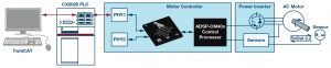
Figure 8. Implementation of a synchronization scheme.
The main elements of the motor controller are the fido5200 and ADSP-CM408, both from Analog Devices. Together the two provide a highly integrated chip set for a network connected motor drive.
fido5200 is a real-time Ethernet multiprotocol (REM) switch with two Ethernet ports. It provides a flexible interface between a host processor and the industrial Ethernet physical layer. fido5200 includes a configurable timer control unit (TCU) that makes it possible to implement advanced synchronization schemes for the various industrial Ethernet protocols. Additional functions like input capture and the output of square wave signals can also be realized via dedicated timer pins. Timer input/output are kept in phase with the synchronized local time and therefore with the network traffic. This makes it possible not only to synchronize the I/O of a single slave node, but the slave nodes across the whole network.
The REM switch has two Ethernet ports and hence connects to two Phys (PHY1 and PHY2). This topology supports both ring and line networks. However, in the experimental setup, only one slave node is used for illustration and only one Ethernet port is active.
The REM switch communicates with a host processor though a parallel memory bus, which ensures high throughput and low latency.
The host processor used to realize the motor controller is the ADSP-CM408. It is an application specific processor based on an ARM® Cortex®-M4F core to implement control and application functions. The processor includes peripherals to support industrial control applications such as timers for PWM inverter control, ADC sampling, and position encoder interfaces. To keep all peripherals in sync with the network, a flexible trigger routing unit (TRU) is utilized. The TRU redirects the triggers generated by the fido5200’s TCU to all timing critical peripherals on the ADSP-CM408. These are the pulse-width modulator, sinc filter for phase current measurement, ADC, and absolute encoder interface. The principles behind synchronizing I/Os are illustrated in Figure 9.
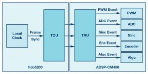
Figure 9. Generating synchronization events for I/Os.
In Figure 9, notice how the I/O event scheduler is realized using the TCU on the REM switch and the TRU on the motor control processor. In other words, the function is implemented across two integrated circuits.
The feedback for the motor controller is phase current and the rotor position from a 3-phase servo motor. Phase current is measured using isolated Σ-Δ ADCs and the rotor position is measured with an EnDat absolute encoder. Both the Σ-Δ ADCs and the encoder interface directly to ADSP-CM408 without the need for any external FPGA or CPLD.
The PWM switching frequency is 10 kHz and the control algorithm is executed once per PWM period. As discussed in this article, the TCU provides synchronization pulses to ADSP-CM408 once per PWM period.
Experimental Results
A photo of the experimental setup is shown in Figure 10. To illustrate the synchronization of the system the PLC was setup to run a program with a task time of 200 μs. The task time also determines the frame rate on the EtherCAT network. The motor controller runs with a PWM and control update period of 100 μs (10 kHz) and therefore needs synchronization pulses to happen at this rate. The result is shown in Figure 11.
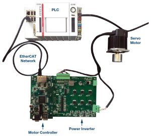
Figure 10. Implementation of a synchronization scheme.
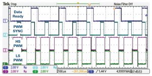
Figure 11. Generating synchronization events for I/Os.
The signal Data Ready indicates when the REM switch has made network data available to the motor control application. The signal is asserted every 200 μs, which corresponds to the EtherCAT frame rate. The PWM sync signal is also generated by the REM switch and used to keep the I/O of the motor controller in synchronism with the network traffic. Since the PWM period is 100 μs, the REM switch schedules two PWM sync pulses per EtherCAT frame. The lower two signals on Figure 11, HS PWM and LS PWM, are high-side and low-side PWM for one of the motor phases. Notice how the PWM signals are synchronized to the network traffic.
Summary
Real-time Ethernet is widely used in motion control systems and some protocols achieve time synchronization with an accuracy of sub-1 μs. However, the synchronization only involves data traffic between the network master and slaves. Existing network solutions do not include synchronization of motion control I/O, which limits the achievable control performance.
The synchronization scheme proposed in this article enables synchronization all the way from the network master right down to the motor terminals. Because of much improved synchronization, the proposed scheme offers significant improvement in control performance. The proposed scheme also offers seamless synchronization across multiple axes. Axes can easily be added and the synchronization tailored to the individual motor controller.
The synchronization is based on an I/O event scheduler, which resides between the network controller and the motor controller. The I/O event scheduler is programmable on the fly and can be conditioned to minimize the effect of jitter/frequency changes.
The article’s proposed scheme has been verified in an experimental setup and results were presented. EtherCAT was used as the communication protocol in the experiment. However, the ideas presented apply to any real-time Ethernet protocol.
References
1 Jie Ma. “Multi-DOF Motion Control System Design and Realization Based on EtherCAT.” 2016 Sixth International Conference on Instrumentation and Measurement, Computer, Communication, and Control, July 2016.
Jens Sorensen [jens.sorensen@analog.com] is a system applications engineer at Analog Devices, where he works with motor control solutions for industrial applications. He received his M.Eng.Sc. degree from Aalborg University, Denmark. His main interests are control algorithms, power electronics, and control processors.
Dara O’Sullivan [dara.osullivan@analog.com] is a senior system applications engineer with the Motor and Power Control team (MPC) within the automation, energy, and sensors business unit at Analog Devices. His area of expertise is power conversion and control in ac motor control applications. He received his B.E., M.Eng.Sc., and Ph.D. from University College Cork, Ireland, and has worked in industrial and renewable energy applications in a range of research, consultancy, and industry positions since 2001.
Christian Aaen [christian.aaen@analog.com] is a software systems design engineer with the Deterministic Ethernet Technology Group at Analog Devices. His area of expertise is embedded software design with a background in power conversion and motor drives. He received
