

Many components in modern smartphones communicate with each other via interfaces standardized by the MIPI Alliance. Developers can analyze signal integrity and data content on these interfaces with an oscilloscope. But you need a low-noise oscilloscope with a very high dynamic range and some relevant software tools.
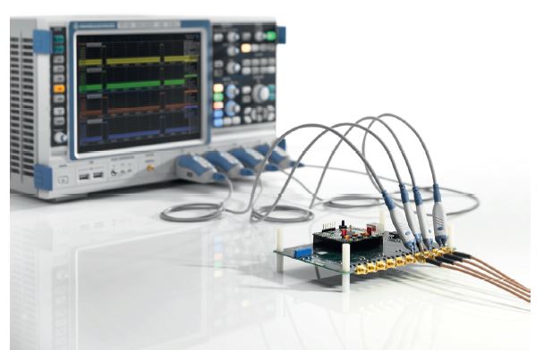
Fig. 1: The R&S RTO oscilloscopes’ outstanding RF
characteristics and their numerous debugging functions for
MIPI interfaces save time during development
(source: Rohde & Schwarz).
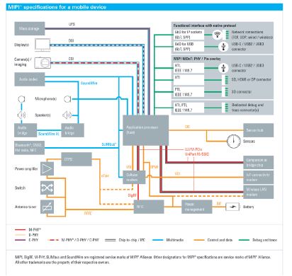
Each new generation of modern mobile phones enters the market with new features such as additional sensors, higher display resolutions and an extended range of equipment. The numerous components inside these devices communicate quickly and efficiently via common interfaces to offer smooth functionality. The most widely used standards for hardware and software interfaces in mobile phones are from the non-profit MIPI Alliance, which consists of more than 280 member companies. According to the MIPI Alliance, at least one of their standards is implemented in every modern smartphone and in about 90 % of all classic mobile phones. The MIPI standards, which are constantly evolving, are also used in tablets and digital cameras as well as products for the automotive and health care sector. Fig. 2 shows the current status.
The standard framework defines three physical layers: D-PHY, C-PHY and M-PHY (Fig. 3). These physical layers are optimized for high-speed (HS) data transmission while maintaining low power (LP) consumption. This optimization places special demands on test equipment during development.
The physical layers – specifications and use
D-PHY, the most commonly used specification, supports camera and display applications. The recently published specification for C-PHY describes an efficient unidirectional streaming interface with low-speed, in-band reverse channel, which should replace D-PHY for higher speed requirements in the future. The third specification, M-PHY, supports a broader range of applications, including interfaces for display, camera, audio, video, memory, power management and interchip communications, for example, between baseband chips and those for RF. In addition, it was adopted as a physical layer for protocols outside of the MIPI ecosystem such as Mobile PCIe (M-PCIe) and SuperSpeed Inter-Chip (SSIC) USB.
 Several higher-level protocols are specified for each physical layer (Fig. 3). Presently, the variants based on C-PHY are barely used. The Unified Protocol (UniPro) specification makes it possible to use the similarities for higher-layer protocols based on M-PHY for interconnecting components within mobile devices. The specification is suitable for a wide range of components including application processors, co-processors and modems, as well as different types of data traffic including control signals, user data transfer and packetized streaming.
The Rohde & Schwarz’ R&S RTOs for example are oscilloscopes which the user can configure perfectly for analyzing MIPI interfaces. They offer different software options for analyzing MIPI-based protocols and their respective physical layers (Fig. 4). The following sections describe how a R&S RTO effectively handles all T&M requirements of the MIPI standards. Although both the D-PHY and M-PHY MIPI standards serve as examples, the arguments also apply to the other MIPI options offered by the R&S RTO.
Detailed analysis of the physical layer
When analyzing the physical layer, it is essential to differentiate between the DUT’s signal integrity and the signal fidelity of the test equipment. Critical oscilloscope parameters include noise, jitter, DC accuracy and bandwidth limitations at high amplification factors. The acquisition of consecutive LP and HS sequences, which have very different signaling levels, is particularly challenging. They require a high signal integrity in order to determine signal quality – especially for the HS components. Fig. 5 shows the respective voltage levels.
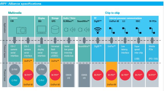
Fig. 3: Applications, protocols and physical layers of the MIPI standards (source: MIPI Alliance).
The better the characteristics of the T&M instrument at hand, the greater the tolerance range for the DUT, resulting in cost savings, lower scrap rates and more efficient measurements. Thanks to its excellent features, this is where the R&S RTO excels – as shown in the following examples.
Simultaneous acquisition of 200 mV and 1.2 V voltages
When characterizing the physical layer, a full scale of 1.4 V is used to acquire the LP signal. 8-bit A/D converters as used in most oscilloscopes provide a full-scale resolution of 5.5 mV/bit. While this is theoretically sufficient for measurements on the 200 mV signal (assuming an ideal A/D converter), additional influences might render it insufficient. In practice, the A/D converter’s effective number of bits (ENOB) is reduced by several influences such as offset error, gain error, nonlinearity error and static noise. The R&S RTO oscilloscopes benefit from their low-noise frontend and precise A/D converters. The converters provide an unmatched dynamic range of > 7 bit (ENOB) that can be fully utilized over the full instrument bandwidth of 4 GHz.
In addition, the R&S RTO oscilloscope’s low noise reduces the influence of noise floor on the measurement. For example, actual RMS noise at the selected full scale of 1.4 V (i. e. 140 mV/div), is only about 5.0 mV. This value can be significantly higher on other oscilloscopes. The high dynamic range of the R&S RTO and its low inherent noise increase measurement accuracy, thereby reducing the rate of rejected DUTs
Overloading the frontend
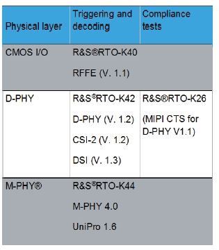
Fig. 4: Overview of MIPI standards
covered by the R&S RTO
oscilloscopes’ analysis options
(source: Rohde & Schwarz).
One workaround to reduce the oscilloscope’s influence on HS signal measurements is to use higher amplification. Using a full scale of 300 mV, for example, increases the resolution to 1.2 mV/bit and reduces RMS noise to 1.1 mV. The disadvantage to this approach is that the amplifier in front of the A/D converter needs recovery time if operated outside its specified range. During this period, the energy stored in the amplifier causes signal distortions and makes results useless. Using this approach would only make sense if the signal of interest occurs much later than the transition from the LP to the HS state. The exact time needed for this is usually not specified by manufacturers but is typically in the range of several nanoseconds.
Even if an overloaded amplifier does not affect the area of interest, problems may still arise because many oscilloscopes limit the bandwidth for high amplifications in order to reduce noise. These limitations are often drastic and can go down to 500 MHz for the highest amplifications. Since the D-PHY standard requires rise and fall time measurements in the range of 100 ps, oscilloscopes with a bandwidth of at least 3.5 GHz are necessary. With an input sensitivity of 30 mV/div and a typical active probe with an attenuation factor of 10:1, the frontend must be set to 3 mV/div in order to capture the full range of the 200 mV differential signal. The bandwidth of most oscilloscopes is insufficient when set to this value. Thanks to its low-noise frontend and powerful A/D converters, the R&S RTO oscilloscope’s full instrument bandwidth down to 1 mV/div is available, offering the highest dynamic range for compliance measurements (Fig. 6).
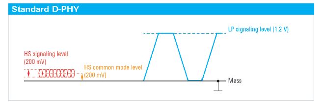
Fig. 5: Voltage levels of the MIPI D-PHY signal (source: Rohde & Schwarz).
In addition to these technical details, an intuitive workflow quickly leading to results is crucial when performing compliance measurements. The R&S ScopeSuite (Fig. 7) and the respective R&S RTO-K26 compliance test option offer quick results. Step-by-step instructions and descriptive pictures ensure that measurements succeed on the first try. In addition, the R&S RTO-K26 compliance test option uses the numerous possibilities of the oscilloscope’s digital trigger system’s numerous possibilities to quickly isolate the right signals and reduce measurement time.
Data communications between components
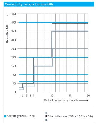
Fig. 6: The R&S RTO oscilloscope
offers full measurement
bandwidth at every input
sensitivity, even at 1 mV/div
(source: Rohde & Schwarz).
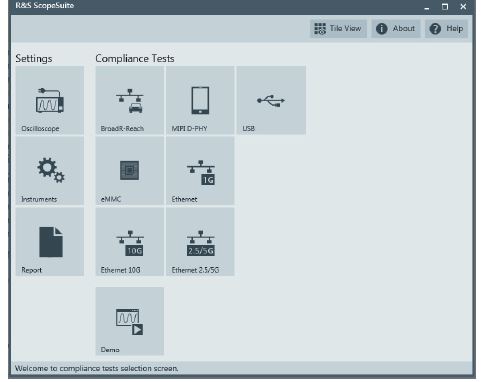
Fig. 7: The main screen of the R&S ScopeSuite
shows the available compliance tests
(source: Rohde & Schwarz).
After verifying signal integrity, the next step in design development is to analyze and debug communications between different components. Oscilloscopes with MIPI triggering and decoding options for serial communications protocols, such as those available for the R&S RTO (Fig. 4), greatly simplify these measurements.
The R&S RTO-K44 option, for example, supports debugging directly on the lowest physical M-PHY layer as well as on the higher UniPro based protocol layers. The 4 GHz R&S RTO2044 covers UniPro 1.6 up to HS transmission mode gear 2 (HS-G2, 2.9 Gbit/s), making it possible to debug protocols such as CSI-3, UFS and UniPort-M.
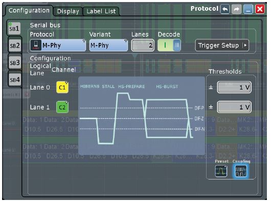
Fig. 8: Configuration of M-PHY / UniPro protocol
decoding (source: Rohde & Schwarz).
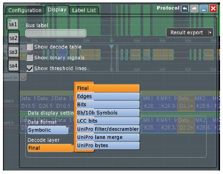
Fig. 9: Selection of the decoded layer (source: Rohde & Schwarz).
To setup the decoding of a two-lane M-PHY signal, two differential probes (R&S RT-ZD40) are connected to channel 1 and 2. A dialog box guides the user through the configuration (Fig. 8). Users simply need to select either M-PHY or UniPro and set the number of lanes (up to four lanes are supported). Both coupled and individual threshold values can be used.
The data format and the layer to be decoded is set in a second step. Being able to choose layers is useful for debugging errors on different protocol levels, starting from the edge transitions, to the bits and symbols, up to the upper UniPro protocol layers (Fig. 9).
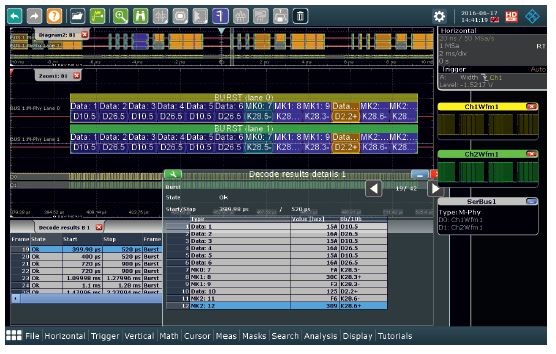
Fig. 10: M-PHY layer decoding results with zoom and
table display the details of the frames and bursts
(source: Rohde & Schwarz).
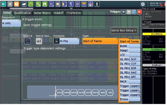
Fig. 11: M-PHY / UniPro protocol decoding setup
(source: Rohde & Schwarz).
In Fig. 10, the setup and activated decoding illustrate the different bursts for data and markers (MK0, MK1, MK2). The decoding table provides an overview of the bursts. A second table provides details of the data (decode results details 1) for an in-depth analysis of individual bursts. Protocol-dependent triggering of the R&S RTO-K44 option separates the respective data telegrams from one another (Fig. 11). Use of the fast and precise digital triggers, in combination with additional software selection, results in an extremely high-performance workflow.
Summary
Thanks to the triggering and decoding as well as compliance test options, the R&S RTO oscilloscopes cover all measurements in line with the MIPI standards. Their outstanding RF characteristics and convenient operation enable development engineers to achieve better results in a shorter time.
