
Designers in the telecommunications, high-performance computing, and medical industries face ever-changing electrical and mechanical interconnect requirements. These industries are driven by increasing data rates, denser systems, and shrinking product footprints.
Fortunately for designers in other sectors, like industrial, motion control, and some military applications, interconnect requirements do not change as quickly. Reasons for this include longer product life cycles, lighter bandwidth requirements, and designers do not face constant pressure to reduce product size, among other reasons.
Designers in industrial markets are generally not too concerned with high-speed interconnects. Ethernet is usually the maximum bandwidth requirement.
Many industrial EOEM designers use the word “rugged” to describe their board-level interconnect needs. While “rugged” can mean different things to different people, it usually includes the ability to withstand high shock and vibration applications, maintain mechanical and electrical integrity after exposure to harsh environments and after high mating cycles, and provide EMI shielding attributes, to name a few.
Several design elements contribute to a connector being called “rugged,” including the contact design, plating, and insulator design.
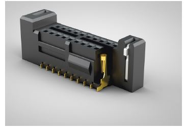
Rugged design features can make
micro pitch interconnects rugged by
incorporating BeCu contacts, weld tabs,
latches, and locks
INSULATOR DESIGN
Examples of plastic insulator design features that are popular with industrial product designers include:
Board locks on connectors that mechanically lock two PCBs together.
Positive latching systems on discrete wire and IDC cable systems. Manually activated latches can increase unmating force by up to 200%.
Screw downs which secure the connector mechanically to the board.
Weld tabs, which significantly increase shear resistance of the connector to the PCB.
Dust and water protection are often a concern; IP ratings such as IP67 and 68 are frequently required.
Space does not allow us to discuss the innumerable insulator design permutations such as insulator material, heat deflection temperature, maximum processing temp, RoHS compliance, or dielectric strength, among countless other considerations.
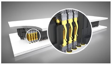
Contact geometry, orientation, and placement in the
insulator can improve signal integrity performance and
life cycle
CONTACT DESIGN
We will limit our brief discussion to contact base materials and design for rugged applications. Common base metals include brass, phosphor bronze, and beryllium copper.
Brass is the least expensive of the three metals and has excellent electrical properties. Having said that, Samtec recommends not using brass in contacts (receptacles) in a working beam because it could fail due to low yield strengths.
Phosphor bronze is stronger than brass and has better spring properties. It is excellent for contacts that have relatively few mating cycles and low contact flexure.
Beryllium copper (BeCu), while more expensive than most contact materials, provides the best combination of mechanical and electrical properties. Once formed and hardened, BeCu will retain its shape under a wide variety of conditions.
At Samtec, two contact systems are most popular for industrial applications. First is a multi-finger, heat-treated BeCu system contact. This is commonly used in 1.27 and 2.00 mm pitch systems. Although these are micro interconnects systems, the contact is designed for rugged environments. For example, a slot in the tail allows more surface area for solder adhesion. Also, connectors with micro tail slots tend to adhere to the wet solder paste prior to reflow better than flat leads. All of this increases the mechanical strength of the connector to the PCB.
Also notice the slot in the transition area between the gull-wing tail and the contact. This slot, while seldom needed, is designed to prevent solder wicking. While wicking is rare in SMT applications because of the limited amount of solder, if it should occur, the slot disrupts the capillary action so the solder does not migrate into the contact area.
Second is a dual wipe, phosphor bronze tuning fork design. This design is popular in rugged applications because of the contact geometry. Specifically, the length of the two mating beams (fingers) allows firm, consistent normal forces, and is less likely to take a permanent set after exposure to numerous cycles.
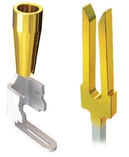
Multi-finger, heat treated BeCu contact for high cycle, high reliability applications
Phosphor Bronze, long-beam contact for shock and vibration applications
BANDWIDTH
While system speed is not a concern for most industrial EOEM designers, for some it may become a concern in the future. Industrial Ethernet is usually the maximum bandwidth requirement.
Contact systems can be designed to meet both rugged and higher bandwidth requirements. One popular design incorporates BeCu to maximize spring properties, while the contact geometry and orientation in the insulator optimizes signal integrity. Specifically, the surface of the contact is milled, creating a smooth mating surface area instead of a stamped contact that mates on a cut edge. This smooth mating surface reduces the wear tracks on the contact increasing the durability and cycle life of the contact system. It also lowers insertion and withdrawal forces allowing the connectors to be zippered when unmating.
The contacts are positioned in the plastic insulator so the narrow edges of the pins are parallel to each other. This minimizes the parallel surface area reducing broadside coupling and crosstalk.
PLATING
Designers frequently ask what plating finish we recommend. The best plating finish is whatever material meets your requirements at the lowest cost. Gold is generally specified for high cycle and high reliability applications, or in low voltage or low current applications. Even in very hostile environments, it will remain free of oxides which could cause an increase in contact resistance.
Tin is a lower cost alternative and has excellent solderability. It is used in connector systems where fewer cycles are expected. Tin is also used in high normal force contacts which cause sufficient wiping action during lead insertion to help break the tin oxide surface film.
Selective gold-tin plating is Samtec’s most popular plating option because it provides designers with the best of both worlds. The critical contact area has the reliability of gold, and the tail has the lower cost and solderability of tin.
In conclusion, interconnect systems do not meet industrial performance requirements by chance. The connector insulator, contact system, and rugged features must allow it to withstand high mating cycles, high reliability, and harsh environment applications. Also, rugged contacts and insulators, often on a smaller centerline, are designed to meet higher bandwidth requirements.
