

Introduction
Mini-Circuits’ YAT-D-series MMIC attenuator dice (RoHS compliant) are fixed value, absorptive attenuators fabricated using highly repetitive MMIC processing with thin film resistors on GaAs substrates. They contain through-wafer Cu metallization vias to realize low thermal resistance and very wideband operation. YAT attenuator dice are available from stock with nominal attenuation values of 0 to 10 dB (in 1 dB steps), and 12, 15, 20, and 30 dB. YAT die are specified to operate to 26.5 GHz with excellent attenuation flatness and Return loss.
However, the specified performance is characterized with a continuous ground plane underneath the entire die. A simple modification to the ground plane allows the attenuator to achieve excellent return loss and attenuation flatness up to 40 GHz. In this article, we explain this method of expanding the usability of YAT-D MMIC attenuator dice for applications up to 40 GHz.
-

- Figure 1: Die Dimensions and Bonding Pad Positions
-
- Figure 2: Assembly Diagram
-
- Figure 3: Modification to ground plane to reduce capacitance.
-
- Figure 4 Combined and Split Ground under DUT
-
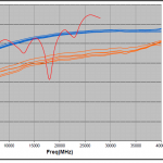
- Figure 5: S11 vs. Frequency of Combined Ground and Split Ground
Modification to Expand Performance to 40 GHz:
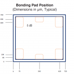
Figure 1 shows the mechanical dimensions and bonding pad positions of a YAT-D attenuator die. Table 1 summarizes the critical dimensions of the die, and Table 2 shows the Die ID of the entire family of YAT dice.
Figure 1: Die Dimensions and Bonding Pad Positions
| Table 1 Critical Dimensions of the Die | Table 2 Die ID
|
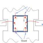
Figure 2 shows the Assembly Diagram with a solid, continuous ground plane underneath the die. In this arrangement, YAT-D series dice perform superbly to 26.5 GHz. At higher frequencies, however, the attenuator performance degrades due to parasitic effects between the die and the ground plane.
Figure 2: Assembly Diagram
Table 3 Recommended Wire Lengths
| Wire | Wire Length (mm) | Wire Loop Height (mm) |
| All wires | 0.25 | 0.15 |
The die and the ground plane essentially form parallel conductive plates which create unintended capacitance expressed by the parallel plate capacitance equation (1) below.
(1)
Where the permeability of the material between the two plates
the overlapping surface area of the plates, and
the distance between the plates (PCB thickness)
-
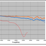
- Figure 6: S21 vs. Frequency of Combined Ground and Split Ground
-
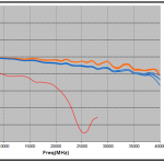
- Figure 7: S12 vs. Frequency of Combined Ground and Split Ground
-
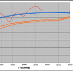
- Figure 8: S22 vs. Frequency of Combined Ground and Split Ground
Capacitive reactance becomes smaller and smaller as frequency increases above 26.5 GHz, and the attenuator becomes increasingly sensitive to the capacitance between the die and ground plane at high frequency. This effect is primarily what limits the frequency range of the attenuator die. Reducing the capacitance between the die and the ground plane, however, would expand performance to higher frequencies.
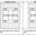
It is evident from equation 1 that capacitance is inversely proportional to the gap, between the two plates – in this case, the distance between the top of the die and the bottom of the ground plane. Therefore, one way to reduce the capacitance is by widening that gap. This is achieved by creating a small trench in the ground plane 0.5µm deep and 0.25 µm wide, running directly under the series signal path. The modified ground plane is represented in Figure 3, and the layout of the die on both continuous and split ground planes is shown in Figure 4.
Figure 3: Modification to ground plane to reduce capacitance.
Figure 4 Combined and Split Ground under DUT
Note that the width of the gap in the ground plane is very small, and application of conductive epoxy must be such that the integrity of the split is maintained in order to achieve the desired effect.
Qualifying Performance to 40 GHz
To validate the performance of YAT-D dice with split ground to 40 GHz, a sample of 5 YAT-D dice were tested on continuous ground plane and another 5 were tested on a split ground plane. Input/output insertion loss, input/output return loss and insertion loss flatness were measured from DC to 40 GHz. The split ground improved the return loss at 40 GHz from 13 dB to 19 dB typical and insertion loss flatness to from ±0.7 dB to ±0.5 dB. The test results are presented in Figures 5 – 8 and in Table 4. Figures 4 – 7 include the performance of a packaged YAT attenuator for reference.
Table 4 Tabular Summary of Performance: Split vs. Combined Ground.
| YAT-3-D+ | Freq (MHz) | 5 Units of YAT-3-D+ Split Ground | 5 Units of YAT-3-D+ Combined Ground | ||||||
| From | To | Min. | Avg. | Max. | Min. | Typ. | Max. | ||
| Input Return Loss (dB) | 10 | 5000 | 38.0 | 48.2 | 54.4 | 25.6 | 41.6 | 47.7 | |
| 5000 | 15000 | 27.7 | 34.0 | 41.7 | 16.6 | 21.0 | 26.8 | ||
| 15000 | 18000 | 26.1 | 29.1 | 31.1 | 15.4 | 16.7 | 17.8 | ||
| 18000 | 27000 | 23.1 | 26.5 | 29.4 | 13.2 | 14.8 | 16.6 | ||
| 40000 | 40000 | 18.5 | 19.4 | 21.0 | 12.3 | 13.0 | 14.2 | ||
| Output Return Losss (dB) | 10 | 5000 | 36.9 | 51.5 | 59.9 | 25.4 | 39.9 | 44.8 | |
| 5000 | 15000 | 27.7 | 32.8 | 40.9 | 16.4 | 20.8 | 26.5 | ||
| 15000 | 18000 | 26.4 | 27.9 | 30.1 | 15.3 | 16.5 | 17.6 | ||
| 18000 | 27000 | 23.1 | 25.5 | 28.6 | 13.1 | 14.6 | 16.4 | ||
| 40000 | 40000 | 18.0 | 19.2 | 20.0 | 12.2 | 13.2 | 14.4 | ||
| RETURN LOSS (Worse of In & Out) (dB) | 10 | 5000 | 36.9 | 48.2 | 54.4 | 25.4 | 39.9 | 44.8 | |
| 5000 | 15000 | 27.7 | 32.8 | 40.9 | 16.4 | 20.8 | 26.5 | ||
| 15000 | 18000 | 26.1 | 27.9 | 30.1 | 15.3 | 16.5 | 17.6 | ||
| 18000 | 27000 | 23.1 | 25.5 | 28.6 | 13.1 | 14.6 | 16.4 | ||
| 40000 | 40000 | 18.0 | 19.2 | 20.0 | 12.2 | 13.0 | 14.2 | ||
| Insertion Loss In-Out (dB) | 10 | 5000 | 3.0 | 3.0 | 3.1 | 3.0 | 3.0 | 3.0 | |
| 5000 | 15000 | 3.0 | 3.1 | 3.2 | 3.0 | 3.1 | 3.3 | ||
| 15000 | 18000 | 3.1 | 3.1 | 3.2 | 3.2 | 3.3 | 3.3 | ||
| 18000 | 27000 | 3.1 | 3.2 | 3.3 | 3.3 | 3.5 | 3.7 | ||
| 40000 | 40000 | 3.4 | 3.6 | 3.7 | 4.0 | 4.3 | 4.5 | ||
| Insertion Loss Out-In (dB) | 10 | 5000 | 3.0 | 3.0 | 3.1 | 3.0 | 3.0 | 3.0 | |
| 5000 | 15000 | 3.0 | 3.1 | 3.2 | 3.0 | 3.1 | 3.2 | ||
| 15000 | 18000 | 3.1 | 3.1 | 3.2 | 3.2 | 3.3 | 3.4 | ||
| 18000 | 27000 | 3.1 | 3.2 | 3.3 | 3.3 | 3.5 | 3.6 | ||
| 40000 | 40000 | 3.8 | 4.0 | 4.1 | 4.1 | 4.4 | 4.7 | ||
| INSERTION LOSS Worse of In-Out/Out-In (dB) | 10 | 5000 | 3.0 | 3.0 | 3.1 | 3.0 | 3.0 | 3.0 | |
| 5000 | 15000 | 3.0 | 3.1 | 3.2 | 3.0 | 3.1 | 3.3 | ||
| 15000 | 18000 | 3.1 | 3.1 | 3.2 | 3.2 | 3.3 | 3.4 | ||
| 18000 | 27000 | 3.1 | 3.2 | 3.3 | 3.3 | 3.5 | 3.7 | ||
| 40000 | 40000 | 3.8 | 4.0 | 4.1 | 4.1 | 4.4 | 4.7 | ||
| Insertion Loss Flatness (dB) | 10-27000 | 10-27000 | 0.1 | 0.1 | 0.2 | 0.3 | 0.3 | 0.3 | |
| 10-40000 | 10-40000 | 0.4 | 0.5 | 0.5 | 0.6 | 0.7 | 0.9 | ||
Conclusion
Mini-Circuits’ YAT-D series MMIC attenuator dice provide precise fixed value attenuation with excellent flatness from DC to 26.5 GHz. For higher-frequency applications, the simple modification to the ground plane demonstrated here enables superb performance up to 40 GHz, making YAT-D series an extremely versatile building block for a vast range of systems.


