
Enhanced Mode GaAs PHEMT (E-PHEMT) based MMIC amplifiers provide users advantages in both broadband noise figure and intermodulation performance, setting them apart from previous generations of GaAs amplifier designs. Historically known for their extremely low noise figure, PHEMTs have also been used extensively for power applications in the mobile PA market. Recent designs possess a combination of low noise and excellent suppression of intermodulation distortion, which improves both ends of the dynamic range over broad frequency range.
Mini-Circuits lineup of low-noise, high-dynamic-range, MMIC amplifiers includes over 30 unique models in the PSA, PMA and PHA families. These are broadband, single stage, Class A, 50Ω MMIC amplifiers. All offer outstanding noise figure and intermodulation performance. The most recent additions to the PMA family are distinguished through their low noise performance over multi-octave bandwidths and high IP3 performance with low DC power consumption. Table 1 shows key performance parameters for selected models in these amplifier families.

Fig. 1: Simplified block diagram of a fibre optical delay line (FODL)
Characterizing Amplifiers for Complex Waveforms
Radar systems are used in an increasing variety of applications, as demand from autonomous land vehicles and airborne drones adds to existing usage in shipping, weather forecasting, air traffic control (ATC) radar and defence. The use of commercial off-the-shelf (COTS) test and measurement systems has become commonplace in characterising the radar system itself but it also offers advantages in the area that most interests radar operators – target detection and tracking.
Field testing is the traditional approach, but this can prove extremely time-consuming, complex and expensive, and may involve repeatable conditions that are difficult to configure. The alternative is to set up real-life radar test simulations that include many different types of targets and scenarios. In particular target generators need to simulate the range, radial velocity and size of the target, along with environmental factors such as for example precipitation. Radar calculates the range of a reflection from the time delay between transmission and reception. Doppler radars can also estimate the target radial velocity from the frequency shift of transmitted and received signal carrier frequency. Amplitude of the echo signal indicates the object’s size and material.
To ensure an acceptable accuracy and resolution, detection and false alarm rate of the radar system for these functional tests, targets have to be generated over the entire unambiguous range, unambiguous radial velocity interval and azimuth/elevation coverage with different radar cross sections.
Traditional solutions, such as fibre optical delay lines (FODL) or digital radio frequency memory (DRFM), all have their advantages, but also drawbacks such as being specifically designed for only this purpose. COTS measuring equipment can overcome such disadvantages with the ability to perform multiple test and measurement tasks.

Fig. 2: Simplified block diagram of a DRFM system
Traditional radar target generators
FODLs are relatively flexible, phase coherent and small systems that convert the RF signal of the radar to optical and delay it by means of a fibre optical line of a certain length. The signal is then reconverted to RF and retransmitted to the radar. Some systems are also able to introduce Doppler frequency shift.
FODLs offer constant delay versus frequency, are immune to vibration, are largely resistant to electromagnetic interference, and fibre delays do not radiate energy. Repeatability of simulation, low system cost and time-savings are key advantages. Tests where excellent close-in carrier phase noise performance is necessary, such as the fixed target suppression (FTS) test, can be performed very well. However, FODLs cannot generate time-variant range-Doppler targets, nor do they offer continuous range settings or arbitrary signal attenuation and gain.
Unlike optical delay lines, DRFMs manipulate the radar signal digitally – down-converting, filtering and digitising the received RF signal before storing and modifying it. Signals are then reconverted to analogue, and mixed to RF frequency using the same local oscillator (LO) used for down-conversion. A final amplification and retransmission finalises the processing chain.
Developed for electronic countermeasures in military applications, DRFMs that create false targets to mislead the enemys radar and can also be used to simulate real targets for test purposes. Naturally, there is scant commercial and public information available about this classified technology. It is nevertheless known that these systems can cover frequencies up to 40 GHz, offer up to 12-bit digitisation with up to 1.4 GHz of instantaneous bandwidth, up to –65 dBc spurious-free dynamic range with a minimum delay of several dozen ns. Technical constraints limit the ability to combine all these specifications in a single DRFM. Typically, wide bandwidth means a trade-off in signal fidelity or digitisation capability. Furthermore, these specialised target generators come at a high cost. According to the US Department of Defense (DoD), the price of a single DRFM module ranges from USD 150,000 to USD 700,000 [1].
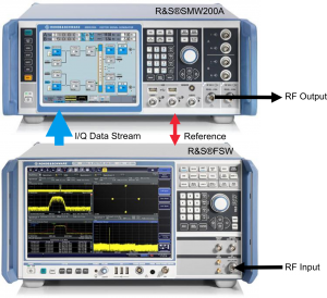
Fig. 3: Representation of a COTS real-time radar target generator (R&S®SMW200A vector signal generator and R&S®FSW signal and spectrum analyser)
The minimum delay introduced by a DRFM is mainly limited by its ADC and DAC. In addition, signal processing adds a number of processing cycles to the radar echo signal. Typical minimum range delays range from below 100 ns to below 1 µs. A further consideration is how the analogue RF signal is represented in the digital domain (amplitude, phase, I/Q) and the number of bits, because this is what mainly determines the DRFM’s signal fidelity. In addition, spurious-free dynamic range (SFDR) may limit the radar’s ability to distinguish real targets from electronic countermeasure signals.
With high signal fidelity, DRFMs having coherent target echo returns are well suited to specific radar tests, but are unsuited to handling a broad variety of signal conditions and scene effects. Cost as well as limited flexibility means they are ill-suited to test the functional parameters of the radar.
Commercial off-the-shelf test and measurement equipment
Today, COTS test and measurement equipment can generate radar targets using similar methods to those of DRFMs: RF down-conversion, digital manipulation in baseband and RF up-conversion. It does so by combining an RF signal analyser as the receiver with a signal generator for the transmitter. Typical systems operate from 100 kHz to 40 GHz and receive any kind of RF radar signal in the specified frequency band with up to 160 MHz bandwidth, then converting the signal to in-phase and quadrature-phase data (I/Q data). I/Q data are applied to the baseband input of the signal generator where time delay, Doppler frequency shift and attenuation are applied to the specified user values. The radar echo signal is then retransmitted to the radar by the signal generator.
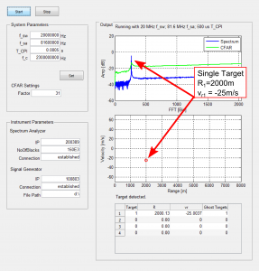
Fig. 4: Single target generated by the COTS radar target generator
One advantage of this measuring equipment is its exceptional RF performance, which is suitable for additional parametric radar tests during research and development or production. The flexible and modular approach allows the vector signal generator or the signal and spectrum analyser to be used in other setups as well – and in their dedicated field installation.
The Fig. 4 above shows the Fast Fourier Transform (FFT) spectrum, range-Doppler plot and target list of a radar under test (RUT). The COTS target generator was setup to generate a single target with a range of 2000 m and radial velocity of -25 m/s. As depicted in the figure above, the radar, which operates with a signal bandwidth (fsw) of 20 MHz and a coherent processing interval (Tcpi) of 500 µs measures the range and radial velocity accordingly.
The COTS radar target generator is able to generate up to 20 different targets at user definable ranges and radial velocities. The signal generator also has multiple RF sources, making it possible to test radar against interference, as for example co-existence with Long Term Evolution (LTE) or other radio-based services [2]. One can also generate arbitrary waveform files and transmit these additional disturbing signals towards the radar in order to test adaptive algorithms like “constant false alarm rate” (CFAR) or other land / sea clutter mitigation techniques.
In addition to testing the functional performance of the radar, the COTS target generator can help assess modern electronic protection measures in the radar, helping to prevent incidents such as the disappearance of aircraft from air traffic control radar caused by military electronic warfare exercises [3]. To test the performance of the radar signal processing a radar waveform is transmitted, delayed and disturbed in the radar target simulator. The radar receiver can tell whether or not the echo return was virtual or real using correlation filters. An uncorrelated signal might result from an ECM system due to resampling at a different rate, a small number of effective bits in the ADC, phase noise or amplifier distortions in the target simulator. When using a DRFM, the generated echo signal fidelity will likely be different than one from a real target. The radar processes focused on electronic protection can detect the differences from the returned echo with different fidelity. This measurement can also be assessed by the presented radar target generator.
Such demonstrations show clearly that COTS test and measurement systems address the test and measurement of radars. In addition, COTS test and measurement equipment is able to generate also radar echo signals with variable range, radial velocity and radar cross section. This combination makes state of the art test equipment very valuable and efficient instruments for radar test.
References
[1] Small Business Innovation Research (SBIR), Navy, Topic N131-006, Acquisition Program, “Direct Digital Radio Frequency (RF) Conversion Digital Radio Frequency Memory (DRFM)”, 2013
[2] Heuel, S.; Roessler, A., “Co-existence Tests for S-Band Radar and LTE Networks”, Microwave Journal – Military Microwaves, August 2014.
[3] Reuters, “Jets vanishing from Europe radar linked to war games”, retrieved from https://www.reuters.com/article/2014/06/13/us-europe-airplanes-safety-idUSKBN0EO1CW20140613, November 2014


