
“With the ATE for SSR we created using NI PXI modular instruments and LabVIEW, our customer reduced radar test time by 90 percent compared to earlier desktop instrument manual connections. Our customer also saved 60 percent of costs compared to other ATEs built with traditional box instruments.”
– Vishwanath Kalkur, Captronic Systems Pvt Ltd
The Challenge:
Using PXI Modular Instruments and LabVIEW for Secondary Surveillance Radar ATE
The Solution:
Using NI PXI modular instruments, along with the NI LabVIEW FPGA Module, to create a customized, scalable solution to test the entire range of radar function.
Unlike primary radars, SSR calculates the range and azimuth of a target, such as an aircraft, using a bidirectional communication link to gather information, including identity, altitude, and country code. Engineers use SSR in both military and civil aviation, with the former incorporating an identifying friend-or-foe system.
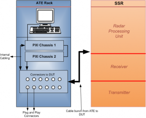
Figure 1- Overall Architecture of ATE to test SSR
SSR works in different modes to obtain information from the target. The system sends interrogating pulses from the radar in a bidirectional rotating antenna at 1,030 MHz. If a target detects interrogation, the transponder of the target replies with a frame of pulses at 1,090 MHz. Radar at the ground station generates interrogating pulses and requests information such as identity, altitude, or country code from the target represented as mode-A/3A, mode-C, or mode-S. Based on the interrogation answers, the aircraft replies with a standard reply pulse format. The system calculates range and azimuth based on the speed-to-distance relation and rotary antenna position with respect to north or the heading direction.
Today’s radars need rigorous testing before they are deployed in military or civil aviation. We developed an ATE using NI PXI modular instruments to facilitate the functionality tests of the radar and physical parameters test of the receiver (Rx) and transmitter (Tx), including Rx bandwidth, Rx sensitivity, Tx power, and Tx pulse parameters. Functionality tests included target simulator to the radar at 1,090 MHz, video signal detection, and radar scan converter display using synthetic transistor-transistor logic (TTL) video signal and LAN communication. Reply pulses in the target and multitarget simulators were stationary and trajectory motion. Figure 1 illustrates the overall architecture of the ATE connected to SSR.
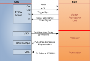
figure 2. detailed-diagram-of-ate-and-ssr
System Overview
We created a system composed of an NI PXI-1042 eight-slot chassis and an NI PXI-8196 embedded controller. We kept the radar either in transmitting mode or receiving mode to test the Tx and Rx functionality. External antenna signals north and azimuth count pulses (ACPs) were generated and simulated through an FPGA board. Target reply pulses were generated through an NI PXI-5671 vector signal generator (VSG) at 1,090 MHz. The system acquired demodulated video signals from the receiver through an oscilloscope card for Rx functionality tests. High-power transmitted RF pulses were acquired through an NI PXI-5661 vector signal analyzer (VSA) to measure Tx signal power and pulse parameters. The synthesized video at the TTL level generated from the radar processing unit was acquired through FPGA digital input and used for a radar scan converter to display the target on a polar plot with its range and azimuth position, info code, altitude, and country code. Figure 2 shows a detailed diagram of the ATE connected to SSR.
Each trigger and sync pulse was synchronized with the interrogating RF pulse of the SSR. To protect the instruments, we switched off the transmitter of the radar during the Rx tests because the radar had a built-in TR module. Both Tx and Rx ports shared the same physical port, which connected to an antenna. The VSA and VSG connected to this same physical port, replacing the antenna and generating and acquiring RF signals at 1,090 MHz and 1,030 MHz.
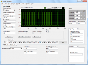
Figure 3- Target Simulator Software Screen
Measurement Parameters
Tx Parameters
Tx out of the radar is connected to the VSA of the ATE with an attenuator. Transmission was a gated sine pulse at RF frequency with a pulse width of approximately 1 µs and pulse repetition time (PRT) of 5 ms.
Tx frequency stability (1,030 MHz + 0.03 MHz)
Pulse peak power (2.0 KW)
Pulse repetition period (ms)
Output power mode and PRF stability
Output power selection and sectoring
Pulse spacing
Pulse shape
Duty cycle (0.01 percent to 66 percent)
Pulse width (µs)
Pulse rise time (ns)
Fall time (ns)
Frequency spectrum
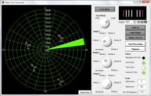
Figure 4- Radar Scan Converter
Rx Parameters
Rx in the radar is received by the RF pulses generated through the VSG, which was synchronized with a trigger/sync pulse. Each sync pulse was synchronized with the interrogating pulse. After receiving a sync pulse to the trigger port of the VSG and FPGA, the RF pulse out was generated through the VSG. The Rx video out was connected to the oscilloscope card to measure the following Rx parameters:
Receiver sensitivity
Receiver bandwidth
Receiver dynamic range
Receiver frequency stability
Phase differential measurements
Reception chain operational sensitivity (STC)
Reception chain side lobe suppression (RSLS)
Functional Test
In the functional test, the system generated the antennal simulation signals, such as north and ACP. It simulated multiple targets at different azimuths and ranges in both stationary and trajectory motion, and represented the transponder’s azimuth and range in a radar scan conversion application.
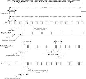
Figure 5- Pulse Formats
Target Simulator
We can conduct proper functional test of an Rx through target simulation using the VSG based on sync pulses. In this case, the ATE acts as a target signal generator coming from the antenna. Each interrogation is synchronized by a trigger pulse connected to both the VSG trigger and the FPGA. Users can configure the range and azimuth to simulate with the target. When a target is ready for simulation, the VSG generates the reply RF pulses of a target after the azimuth count is reached in the FPGA and the next sync trigger is received from the radar. The user can select reply code and mode, and scripted pulses are generated at the specified range and azimuth. Targets are simulated for stationary and trajectory motion. A user configures moving paths at different trajectories. The system can simulate multiple targets at different ranges and azimuths from the same VSG. Different code patterns are applied to the reply pulses as specified by the user. Reply pulses are a sequence of pulses spaced 1 µs apart with a pulse width of 450 ns. Each target’s replies are framed with F1 and F2 pulses at the beginning and end of the sequence. The number of pulses in a frame is derived by the mode of interrogation selected in the GUI. Each sync pulse can have a different mode of reply based on the interrogation mode selected. Such three-reply pulses are separately configurable and can be generated through the VSG with reference to each sync pulse. Figure 5 illustrates reply pulse generation with range delay, azimuth, and code simulation.
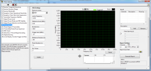
Figure 6- Sequence of Tests
Radar Scan Converter
The system acquires and processes video signals from the radar in the TTL format through the FPGA board. The reply pulses from the target are demodulated in the receiver of the radar and raw video signal is processed in the radar processing unit. This processor provides synthesized TTL pulses that represent the reply frame.
This frame is decoded in the FPGA with a precise width of individual pulses. Because the receiver also picks up noise from the antenna, some unwanted noisy pulses of the desired range are generated out. We developed an algorithm to discard these noise pulses and decode the actual frame. The FPGA then calculates the range and azimuth of the target, with the information code, altitude, and country code of the target.
The system can receive synthetic TTL video using this format: actual target acquired from the antenna, simulated target internally generated in the radar, and target simulated through the VSG base on the interrogation pulse.
Figure 4 shows the scan converter display decoded through the FPGA. Figure 5 illustrates the ACP; north simulation through the FPGA; trigger/sync pulse acquisition; reply pulse simulation based on the range and azimuth selection; acquiring the TTL video signal; and decoding the reply frame.
Modulated pulses from the VSG contain a carrier of 1,030 MHz RF wave.
Antenna Simulation
The north marker pulse generation through the FPGA output and the ACP generation through the FPGA digital output provide antenna simulation. We created a user-configurable GUI based on LabVIEW to set the pulse width, PRT, and azimuth counts per north revolution to simulate antenna parameters.
Software Features
We developed a modular, editable sequence of tests to test total functionality. Users can select either automatic or manual mode for individual parameter test. With a diagnostic panel, users can access the individual PXI instruments for loop-back or self-test. Figure 6 illustrates the sequence of tests present in ATE.
Reducing Radar Test Time With the NI Platform
With the ATE for SSR we created using NI PXI modular instruments and LabVIEW, our customer reduced radar test time by 90 percent compared to earlier desktop instrument manual connections. Our customer also saved 60 percent of costs compared to other ATEs built with traditional box instruments. In addition, the new system replaces the pulse generators and modulator with a single NI PXI VSG, which provides complete functionality test of target simulation, raw video acquisition, and target detection, making it a closed-loop tester.
We plan to upgrade the system to test the redundant six ports of the radar with an automated switching incorporation. We will use an NI PXI-2596 SP6T multiplexer for the upgrade to avoid long cables and connections.
A National Instruments Alliance Partner is a business entity independent from National Instruments and has no agency, partnership, or joint-venture relationship with National Instruments.


