
Introduction: Keeping Up with the Data Deluge
Over the past 20 years, flash memory has been widely adopted in mainstream consumer grade products with relatively short lifetimes, sometimes measured in months, as well as more industrial and commercial devices with lifetimes of years or decades. There are many unique characteristics of flash memory that have fueled its growth across these different market
segments, such as its ability to retain data when power is interrupted. Unfortunately, flash technology has the downside of finite lifespan and lower endurance. Complicating the issue is the fact that hardware and software technologies designed to improve flash life often take a backseat to other seemingly more pressing issues of system design.
This paper discusses the factors that determine when limitations of flash memory lifetime become significant, and presents test data for several common wear-leveling options in Linux.
 Flash Lifetime Metrics
Flash memory lifetimes are described in two primary metrics which are generally touted on the first page of any flash manufacturers’ data sheets:
• Data retention
• Endurance cycles
Data retention is often listed at 20 years for a given operating temperature range. Increased temperature ranges reduce the data retention period which further decrease as the flash memory is used at or near the limits of its specified operating temperatures range. It is important to note that data retention is measured from the time data is successfully programmed.
The second metric, endurance cycles, is a measure of the number of write and erase cycles that the flash memory can endure before becoming unreliable.
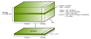
Flash memory is organized into a number of erase blocks or sectors, and each must be erased prior to writing data. A typical erase block is 128KB in size, however depending on the flash part, it may range from 512B to 4,096KB or even more. A given address within an erase block cannot be rewritten without first erasing it. Erase cycles are cumulative and affect only those erase blocks being cycled. In other words, an error in any erase block is constrained to the data of that block.
Erase cycles of SLC flash range from 1,000 to 100,000. While these ranges have an order of magnitude difference, it is the application the flash is placed into that will primarily define the product lifetime.
What is Wear-Leveling?
Wear-leveling is a process to ensure that an entire flash memory device or an array of devices is used in a uniform fashion in order to extend the overall lifetime of the flash.
For a simplistic example of wear-leveling, let’s look at a data recorder with these characteristics:
• Application: The device collects and stores the past 24 hours of field data by simply writing and rewriting the data to the same location on the flash.
• File size of data to be recorded: 128KB
• Erase block size (of the flash): 128KB
• Flash memory endurance: 1,000 cycles With one spare erase block, the device is assumed to use one cycle per day each year:
(1,000 cycles ÷ 365 days) * 1 spare erase blocks = 2.74 years
In this example, it would take about 2.74 years to cycle that one erase sector 1,000 times.
For the data recorder device to accommodate the write erase rules of flash memory, it would have to complete an erase operation to start writing the next day’s set of data. To make the data recorder more robust – to ensure that it doesn’t lose a whole day’s worth of data – we can set aside a second erase block, and erase the first block only after the second set of data was recorded. The resulting side effect is the introduction of a simple wear-leveling scheme.
With two spare erase blocks, the device is assumed one cycle every two days each year:
(1,000 cycles ÷ 365 days) * 2 spare erase blocks = 5.48 years
With these parameters, the period of time prior to cycling the flash to its lifetime has just been increased to almost 5.5 years!
This simple example shows how distributing a fixed set of writes across more flash sectors can increase the period of time prior to cycling the flash to its specified limits. The following sections describe how to account for the important variables associated with wear-leveling techniques, and determine the expected lifetime of the flash in any application.
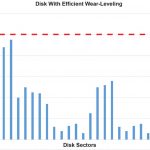
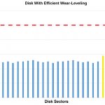
 The figures on the next page depict the concept of wear-leveling. The flash disk in this example has a maximum endurance of 100,000 cycles. Figure 1 represents a disk that does not employ any wear-leveling software, while Figure 2 shows a disk that is managed with wear-leveling schemes. Note that the sectors that have exceeded the 100,000 cycles in Figure 1 are no longer able to store data, and have corrupted the data that they were storing. These sectors represent the high-use areas of the disk. On a FAT disk for example, this may be where the FAT table is stored and corruption here would render the entire file system unreadable. Lower use areas of the disk, which may include application and operating system code, will never reach the flash memory’s maximum endurance. Without wear-leveling, these low-use sectors are essentially wasted flash lifetime. Meanwhile, the disk use in Figure 2 is spread evenly throughout the disk sectors, allowing the flash disk to be reliable for its maximum lifetime.
Professional Wear-leveling Implementation
A properly-executed wear-leveling implementation moves data around in the flash disk to accommodate the fact that flash memory cannot simply be rewritten. The specific algorithms
are beyond the scope of this paper, but the idea is to efficiently write throughout the flash before rewriting the same location.
The wear-leveling scheme implemented by an effective flash manager consists of tracking the number of erases incurred on each flash erase block. In other words, both high and low use sectors are monitored. This is often referred to as dynamic wear-leveling. As erases accumulate,
the difference between the highest and lowest counts is audited. If a specific set of constraints are met, a wear-leveling operation – which swaps the least erased block with the most recently used erase block – is completed.
Two parameters control wear-leveling erases; the first is a maximum difference allowed before wear-leveling erases are incurred, and the second limits the frequency of wear-leveling erases.
Again, considering the necessity to maintain optimal read/write performance in the flash, a flash manager should never incur wear-leveling erases if they are not necessary. It will effectively move high use areas of the flash to low use areas over time and will keep the average erase cycle count within a predefined range. It is important to note that this system utilizes the entire flash disk by forcing static areas of the flash to move, which would otherwise never be rewritten fully.
In order to ensure that the wear-leveling process will not degrade performance or compromise the integrity of fixed file system meta data, the flash manager must begin erases well before the cumulative writes equals the size of the flash disk.
Advanced wearleveling schemes (like
Datalight FlashFX family) keep endurance cycle differences in this example between 700 and 1400, at a maximum.
Simplistic Calculation of Flash Cycles
In order to determine whether a certain application will challenge the endurance cycles of the flash that are specified by the flash manufacturer, a number of variables must be considerd.
Assume the flash is used efficiently by the application and that all flash described by Stotal is available to be written prior to an erase cycle being incurred. Given this assumption, a single erase cycle will be incurred once the entire flash (Stotal) is written. The period of time elapsed
over a given cycle count, and therefore the period of time before a flash chip wears out, is then calculated with the following formula:
P = C [Stotal ÷ ( F * Dwrite) ]
Stotal describes the total flash memory available (KB) to be used as a disk.
Dwrite describes the amount of data (KB) being regularly written into the disk.
F is the frequency of Dwrite to the disk per day.
C is a given number of cycles to calculate the period.
Example – the difference with Static Wear-leveling
In this example, we examine a field data recorder that collects and stores coordinates and other statistics at a rate of 1280 bytes per minute, and must maintain the last hour of data (75KB), for a total of 1800KB of writes per day. This device has 1 MB of flash media total, and the application and configuration files will take up more than half of that space – meaning only 256 KB can be used to store data.
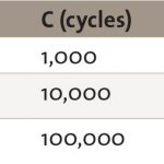
With only dynamic wear-leveling, the media will regularly swap between two 128 KB erase blocks – remember, we cannot erase just 75 KB. The chart below shows three different choices for flash media, rated for the total number of erase cycles. The other values are fixed:
S total = 256 KB, D write = 1800 KB, F = 1 day
If this field recorder’s expected lifetime of 12 years, flash rated for 100,000 cycle flash is required.
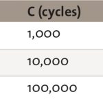
With both static and dynamic wear-leveling, as implemented by the FlashFX family, the entire media is eventually available for data. This results in one change to the equation values above.
S total = 1024 KB, D write = 1800 KB, F = 1 day
For the same expected lifetime of 12 years, flash rated for 10,000 erase cycles is now perfectly appropriate, though a 20-year lifetime would still require flash with 100,000 erase cycles.
Simulation Tests
For purpose of testing the effectiveness of wear-leveling amongst various flash management software, we used the following test:
1. 64MB of NAND Flash configured in small and large block configurations.
a. Small Block – 16KB (4096 blocks)
b. Large Block – 128 KB (512 blocks)
*Large and small block NAND were two different hardware configurations available at the time we performed this test. The results show that the variance of wear-leveling can be greater on large block, because the wear-leveling of static data happens less often.
2. Fill part of the volume with a large file that is not modified. This represents the static data on disk. For the first series of tests, we used 10% static data.
3. Fill remaining portion with another file that is constantly modified. This represents dynamic data
a. Copy data in the file
b. Delete data
c. Repeat above steps for 10,000 cycles
4. Measure the variance in the number of erase counts for blocks on the disk. The smaller the variance, the more effective the wear-leveling technique used
FlashFX Family vs. JFFS2 Results
We measure the effectiveness of wear-leveling algorithms by examining the erase count for each block on the media, then comparing the highest value to the lowest value. We measured this in a situation where approximately 10% of the data on the media was static (placed on the media and not written to again) and compared that to a situation with approximately 60% static data.
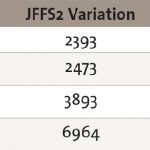
The variance between the highest and lowest values for each test case are shown in this table.
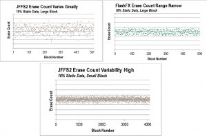
These graphs show the erase count all 512 flash media blocks, over a range of 4000 erase counts. JFFS2 has erase counts which vary greatly within this range, while FlashFX Tera keeps the erase count within a range of roughly 900 erases.
These graphs show the erase count all 4096 flash media blocks, over a range of 8000 erase counts. JFFS2 has slightly better wear-leveling than on large blocks, keeping the erase count within 2500 erases, but FlashFX Tera keeps the erases
on a narrow band of roughly 900 erases.
These graphs show the erase count all 512 flash media blocks, over a range of 4000 erase counts. JFFS2 has erase counts which vary greatly within this range, while FlashFX Tera still keeps the erase count within a range of roughly 900 erases.
These graphs show the erase count all 4096 flash media blocks, over a range of 8000 erase counts. Counts for JFFS2 continue to vary greatly over a range of nearly 7000 erase counts, while FlashFX Tera keeps the erases within a window of 1050 erases.
Conclusions
Typically it takes a very write intensive application to cycle flash memories to their limits. However, it is possible for your product to become a brick sooner than you expect it if the flash limitations are not addressed. Different flash management options within Linux have varying degrees of effectiveness as far as wear-leveling is concerned. When designing a Linux-based embedded device, it is important to understand the data profile of your applications (how often they need to write/erase data from the disk) and evaluate the flash management solution (hardware + software) based on this criteria.


