
Abstract
According to much of the promotional material for digital predistortion (DPD), its performance is based on static quantitative data. Typically, this material shows a DPD spectrum and quotes adjacent channel leakage ratio (ACLR) figures. While this approach addresses fundamental needs, it fails to capture many of the challenges, risks, and performance trade-offs that occur in real-world deployments. The rapid transition to 5G introduces a plethora of new challenges and scenarios that algorithm developers and equipment vendors need to pay more attention to. Underpinning the static performance must be the capability to maintain performance and stability in a complex environment where many elements are in a state of flux.
Introduction
In an ideal world, the output of a power amplifier would be an identical scaled version of the input and the majority of the power used by the amplifier would reside in the output signal. Hence, we would have maximum efficiency and no distortion. In the real world, we fall short: real linear amplifiers tend to have very poor efficiencies. Amplifiers used in cable distribution systems, for example, have excellent linearity, but this comes at the cost of efficiency. In most cases, the efficiency struggles to achieve greater than 6%, with the balance of the power (94%) being wasted. Wasted power has economic, environmental, and application costs. In cellular base stations, electricity accounts for over 50% of the OPEX costs. Wasted power increases electricity usage and produces greenhouse gases, while much of the power that does not get emitted as radio waves has to be dissipated as heat, which necessitates active and passive thermal management.
Over the last several decades, the cellular industry has pushed the efficiency of the PA to a performance level in excess of 50%. This has been achieved by the adoption of smart architectures such as Doherty and advanced process technologies such as GaN. This level of efficiency comes at a cost—linearity. Poor linearity in cellular systems has two principal consequences: in-band distortions and out-of-band emissions. In-band distortions disrupt the fidelity of the transmitted signal and can be represented by a degradation in error vector modulation (EVM) performance. Out-of-band emissions break the 3GPP emissions mask and can cause unwanted interference to operators occupying adjacent channel frequency allocations. We typically measure this aspect of performance in terms of ACLR. GaN PAs offer an additional challenge in that in-band distortions are also produced by the charge-trapping effect. These are dynamic in nature and unrelated to any SNR implied from the ACLR.
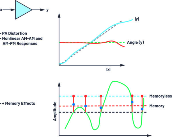
Figure 1. PA dynamic transfer function with memory effects.
Correcting the PA nonlinearity is essential. It is a reasonable assumption that if one knew the transfer function of the PA, employing its inverse on the data would nullify the nonlinearities. However, the PA has what may be considered a dynamic transfer function; its output to input characteristics can be considered to be continuously in flux. Furthermore, the dynamic transfer function is dependent on a combination of the PA characteristics (including power, voltage, and temperature), the input signal presented to the PA, and prior signals that the PA has processed (memory effects). The dynamic nonlinear behavior of the PA needs to be modelled before it can be corrected, hence the requirement for digital predistortion, and the DPD needs to be adaptive to the dynamics of the environment.
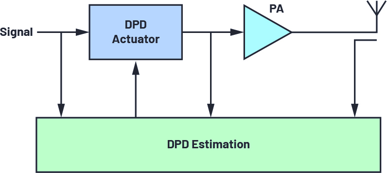
Figure 2. Conceptual representation of a digital predistortion system.
Figure 2 provides the core elements for many DPD systems: observation, estimation, and actuation. The concept in Figure 2 generates a model that tracks the expected response of the PA so that appropriate cancellation signal can be generated to nullify the predicted nonlinear behavior of the PA. There are many models, such as the ubiquitous generalized memory polynomial (GMP).
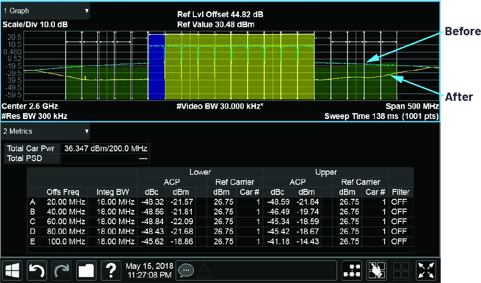
Figure 3. Adjacent channel leakage with and without digital predistortion.
A PA operating in its linear region generates less out-of-band distortions and, as shown in Figure 3, has a notable reduction in the level of noise that leaks into the adjacent channels. Figure 3 shows a screenshot from a spectrum analyzer on a typical DPD test bench used to demonstrate static DPD performance that meets the standards required by many ACLR compliance tests.
Market Evolution, Performance Enhancement, and a Moving Target
DPD has been utilized commercially in cellular base stations since the 1990s, with utilization calculated at over 8 million deployments. As the technology and generational requirements of the cellular market have changed (2G, 3G, 4G, and now 5G), so too have the requirements placed on DPD. Those challenges include, but are not limited to, wider bandwidths, higher powers, carrier placements, higher peak-to-average signal ratios, and densification in the number and proximity of base stations.
Equipment vendors are anxious to differentiate their product offerings and continue to push for performance enhancement in terms of efficiency relative to the relevant 3GPP specification. PA efficiency continues to present a challenge. Whereas traditional drivers of change would have been OPEX costs and thermal management (including the hardware/weight costs associated with it), environmental considerations now provide an accelerant to that change.
PAs and DPD share a partially symbiotic relationship. In some instances, that relationship can be harmonious and in others more difficult. A PA that is DPD friendly with DPD from one supplier may struggle with that from another. Often, optimal performance is achieved when both DPD and PA are configured and tuned to match the specific application. However, PA design is continuously evolving to meet the aggressive requirements of 5G and beyond. In tandem with this, DPD must evolve to meet the extra demands. As wideband and dual-band applications become the norm, PA developers are challenged on how to achieve wider bandwidths at higher frequencies while maintaining performance expectations. Developing a PA with a bandwidth capability of 200 MHz and beyond is a challenge, while ensuring that it can also meet 3GPP specifications and efficiency creates further challenges. Challenges that, in turn, fall back on the DPD developers.
Understanding the Challenge
Quantifying DPD performance is not a straightforward task. There is a matrix of conditions and scenarios that need to be considered—in addition to the PA, there are also a slew of other mitigating dependencies. When we consider performance, the specifics of the test conditions need to be clearly defined: achieving >50% efficiency at a bandwidth of 200 MHz is a much greater challenge than the same level of efficiency at an operating bandwidth of 20 MHz. The situation becomes more complex when we consider carrier placement within the allocated spectrum; it may be a contiguous signal, but it may also be a segmented carrier allocation where portions of the spectrum are occupied.
At a high level, there are quantitative indicators of DPD performance—the data points that are primarily defined by the 3GPP specification or operator requirements: ACLR, EVM, and efficiency. Meeting these are just the tip of the DPD performance iceberg. When stability and robustness are added to the mix, the enormity of the challenge starts to surface. There are two critical aspects to DPD performance: the static bench-level performance and the real-world operational dynamic performance.
To characterize the challenge of dynamics, Figure 4 illustrates signal evolution in a dynamic environment and shows how the ACLR might respond with a continuously adapting DPD. The numbers are notional. The plot provides an example of the effect of abrupt signal changes, which are extreme but legitimate. As the signal changes, the DPD model adapts to it. Adaptation events are indicated as dots. In the transition time between a signal change and the next adaptation, there is a mismatch between the model and the signal and therefore the ACLR value can rise, increasing the risk of exceeding the emissions specification for the duration of the transient.
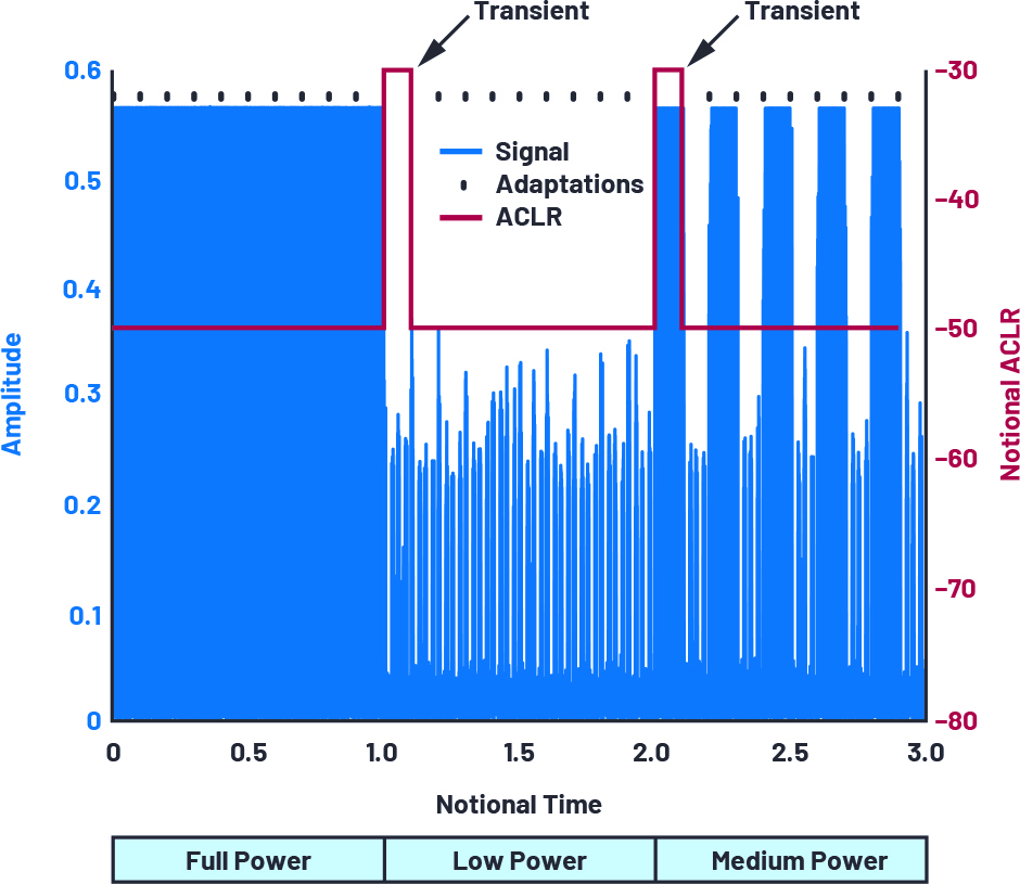
Figure 4. Dynamic cell loading, DPD adaption, and ACLR transients
Adaptation takes a finite time so there will always be a transient. The challenge for high performance DPD is to reduce that model mismatch time to a minimum while also ensuring a smooth transition between both states. The process needs to be managed so that speed of adaptation and disruption to ACLR are both considered. It is important to understand how the model mismatch depends on the nature of the signal transitions. When the mismatch is high, DPD risks degrading performance or, even worse, the stability of the radio. Instability, should it occur, can see the DPD algorithm snowball out of control, blasting emissions masks and, in worst-case scenarios, damaging the radio hardware. On the see-saw of performance vs. stability, stability will always be the prominent design consideration. A DPD design must be robust to ensure stability and error recovery under normal and abnormal operating conditions.
The challenge for a high performance practical DPD solution can be summarized in these requirements:
- Static performance (compliance testing or where the BTS traffic load is approximately constant)
- ACLR
- EVM (including GaN as a special case)
- Dynamics
- Robustness
In addition, since Analog Devices is a third-party vendor of DPD, the following must also be considered:
- Maintenance
- The resolution of performance issues that occur when our customer (the OEM) deploys to its customer (the operator).
- Evolution
- During its lifetime in the field, the PA technology and the signal-space application can change.
- Generality
- An OEM can fine tune its DPD to each product. We do not have that luxury. We must meet the needs of many applications while minimizing configurability and redundancy.
Progressing DPD Performance to Meet the Challenges
Considering static performance alone, there is an element of linear progression to DPD development. If we provide more resources, then we enhance performance. For example, more GMP coefficients help to model the PA behaviors more accurately. Thus, as bandwidths widen, this becomes one element of a strategy to maintain if not improve performance. That approach, however, has its limitations. A point of diminishing returns will be reached where additional resources provide little or no benefit. DPD algorithm developers need to take more creative approaches to eke out further enhancements. ADI’s approach is to augment the base algorithm generalized memory polynomial with more general basis functions and higher order Volterra products. As developers attempt to create a model that will accurately predict the PA behavior, data accumulation and data manipulation are core essential elements. Capturing data at successive time and power levels allows developers a more complete reservoir or armory on which to make their assessments and shape model behavior. Figure 5 provides a conceptual overview of a system adopting such an approach. Note the more extensive data capturing/observation nodes coupled with the digital power monitoring. Power monitoring helps with dynamics. Prior stored models can be brought into play in a variety of ways to mitigate the dynamic transients discussed above.
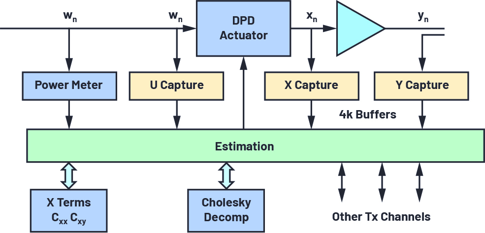
Figure 5. DPD implementation with more extensive data capturing/observation.
In recent years, GaN PA technology has brought about an additional challenge for DPD developers: long-term memory effects. GaN process technology brings with it many distinct advantages in terms of efficiency, bandwidth, and operating frequency. It does, however, exhibit what is known as the charge trapping effect. Charge trapping in GaN is a long-term memory effect, where there is a trap and then a thermal de-trap. GMP-based DPD corrects some of the error. However, there is residual error that continues to impact signal quality. This distortion induces a corresponding rise in EVM. Figure 6 provides a graphical representation of the phenomenon. Note the PA gain fluctuations and the temporal nature of those fluctuations. Also note the trap and de-trap states and that de-trapping occurs on the lower power symbols.
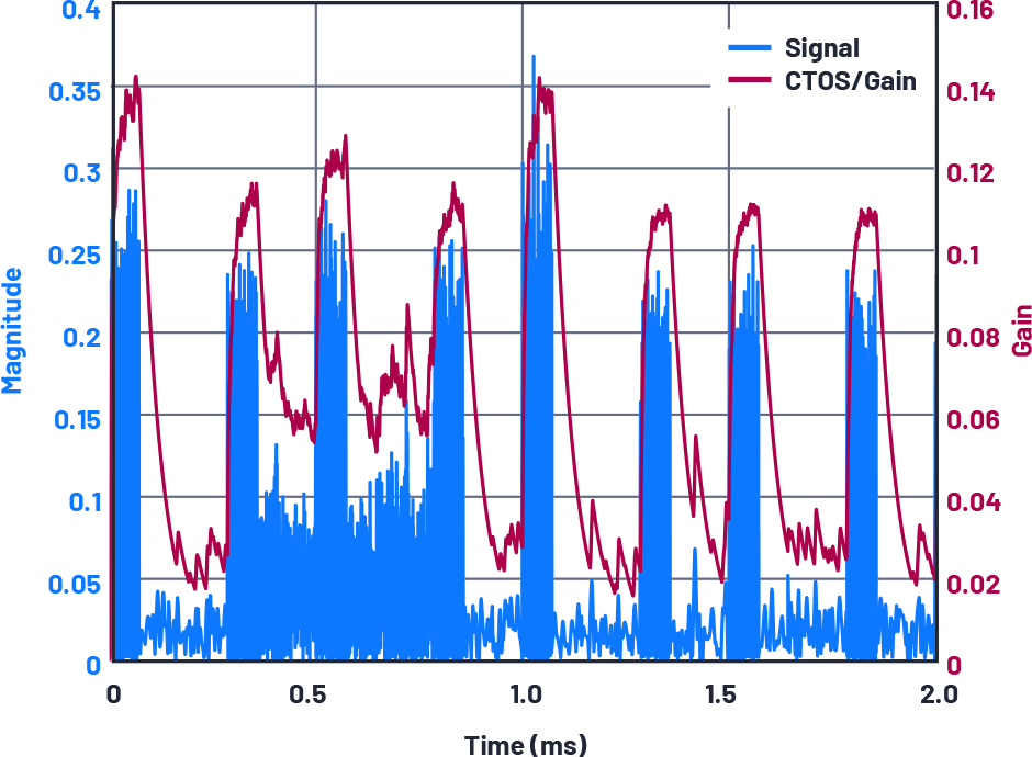
Figure 6. Long-term gain errors introduced by GaN PA charge trapping.
As the temporal effect is long-term, traditional approaches would suggest the acquisition of a very large number of sample points and, hence, a large amount of data to be stored and processed. Memory costs, silicon area, and processing costs mean that this approach is not a feasible option for commercial DPD deployments. DPD developers must negate the effects of charge trapping, but do so in a way that lends itself to efficient implementation and operation. Charge trap correction (CTC) is a feature supported at low cost in terms of power and compute time in our ADRV9029 transceiver. It has been shown to recover the EVM to a level that is within the EVM 3GPP specifications. The next-generation transceiver, the forthcoming ADRV9040, boasts a more elaborate solution that is planned to deliver enhanced performance in dynamic scenarios and better coverage against what are an increasing number of GaN PAs with unique charge trap personalities.
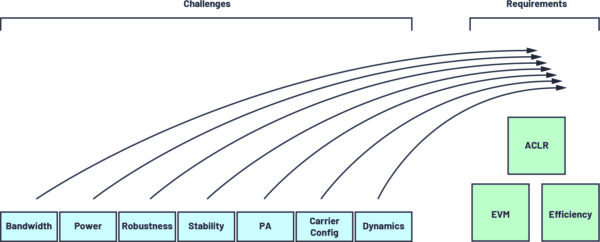
Figure 7. Balancing all the elements of DPD performance with the challenges.
As stated, the stability of a DPD implementation is of utmost importance. Robustness is addressed by continuously monitoring the internal state and providing rapid responses to unusual conditions.
The generality of ADI’s solutions is addressed by testing on a wide sample of PAs from many vendors with many of whom a symbiotic technical relationship is established.
Conclusion
All too often when DPD performance is being presented, the focus is on the static elements of performance. While the yardstick of measurement in terms of EVM and ACLR remain valid, more attention must be paid to the matrix of operating conditions and requirements that frame those measurements. The demands of 5G NR continue to push application requirements. This, coupled with the desire for higher PA efficiencies, compounds the challenge of DPD algorithm development.
As we start to qualify DPD performance, we need a holistic approach that handles:
- Static performance
- Dynamic performance
- Robustness
- Stability
DPD that has narrow margin to the specification may not be welcomed, while DPD that causes temporary specification extrusions may unsettle operators and DPD that goes unstable and results in illegal emissions and possible PA failure is disastrous. A DPD algorithm should not be considered an off-the-shelf item; optimal performance is achieved when the DPD is pruned to the specifics of the PA and the application—hence, algorithm agility and development/field support are also important considerations. An effective DPD algorithm can deliver substantial system benefits. The complexity of the requirements and the performance assessment should not be underestimated.
About the Author
Steve Summerfield is a director at Analog Devices, leading algorithm and architecture development for wireless infrastructure applications. He joined ADI in 2017 having previously held senior positions in various telecommunications and semiconductor companies. Steve also has a long prior career in the university sector. He is widely published, holds many patents, and has a Ph.D. in theoretical physics. He can be reached at steve.summerfield@analog.com.
About the Author
Frank Kearney joined Analog Devices after graduation in 1988. During his time with the company he has held a diversity of engineering and management roles. He currently manages a team of architects and algorithm developers in the Wireless Systems Group. The group’s focus is on transmit path efficiency and system-level enhancements for O-RAN radio architectures. Frank holds a doctorate from University College Dublin. He can be reached at frank.kearney@analog.com.
