
Capacitor charging power supplies are used for pulsed-power applications such as IPL or pulsed lasers for aesthetic medicine and for driving pulsed lasers intended for diverse medical or industrial applications, among many other application fields.
Key parameters for choosing a capacitor charging power supply
The most important parameters which will determine which capacitor charging power supply you will choose and eventually integrate into your product are:
- Electrical parameters
- Physical size
- Reliability
- Price
Among many, the main electrical parameters for choosing a capacitor charger are the following:
- Output power: measured in Joules/Sec (or Watts). It determines how quickly the capacitor will be charged to the required operating voltage.
- Repetition rate: indicates how many times per minute or per second the capacitor can be charged. The higher the rate, the higher the average power the capacitor charging power supply delivers.
- Output voltage rating: Indicates the voltage to which the load capacitor will be charged.
- Input leakage current: a safety parameter indicating the leakage current to Earth. For instance, for most medical applications the leakage current should usually be 0.5mA or less, depending on the device class and required certification.
- User interface, which usually includes as a minimum: Enable/Disable signal for activating the charging power supply, a “Vset” analog control signal for setting the capacitor voltage at the end of charge, an “End-of-Charge” signal, indicating the capacitor is fully charged, and an alarm signal, indicating a malfunction.
Common capacitor charging power supplies technology
The technology used in the capacitor charging power supply has an impact on all the above parameters, especially on its physical size, its reliability and price.
In this paper we will discuss the standard, widely used constant current capacitor charging approach, and we will compare it to Advice Electronics Ltd.’s approach, which allows for smaller size, more reliable and cost-effective quasi-constant-power (QCP) capacitor charging power supplies.
Standard constant current capacitor charging approach
In the range of 1 or 2 KJoule/Sec. and above, most capacitor charging power supplies in the market are built using a constant current capacitor charging approach.
A bit of theory: the voltage (in Volts) across a capacitor is equal to the charge delivered to it (in Coulombs) divided by the capacitor’s capacitance (in Farads). The charge delivered to the capacitor is equal to the integral of the current along the charging period. In this case, since the current is constant, we get a linear voltage charging profile of the capacitor.
Since the power delivered to the load at any moment, in this case a capacitor, is proportional to the output voltage multiplied by the output current, and since the output current is constant and the capacitor voltage increases linearly with time (starting from zero), we conclude that the output power the charging power supply delivers is initially zero, increasing linearly along the charging process.
For instance, let’s suppose we are willing to deliver an energy of 3,000 Joules per second using a constant current charging power supply. At the beginning of the charging process the voltage across the capacitor is zero and accordingly, the power delivered by the charging power supply to the capacitor is zero, then it increases linearly until the charging process is complete (i.e. the desired voltage across the capacitor has been reached).
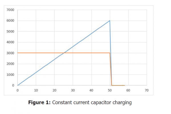
Since the capacitor voltage increases linearly along the charging period, so does the output power delivered by a constant current capacitor charging power supply (blue line), as shown in figure 1.
The energy in Joules delivered to the capacitor is equal to the area below the blue line in figure 1 below (vertical axis in Watts, horizontal axis in mSec.).
Since we require an average energy of 3,000 Joules per second (orange line), and the charging power delivered by the power supply starts from zero and increases linearly, the final, peak charging power the power supply delivers is 6,000 Joules per second, or 6,000W, as shown in figure 1 below.
This approach is simple, and the power supply construction is straightforward, comprising a constant current control loop. However, this approach offers a poor utilization of the power components of the power supply (such as power semiconductors, power transformers and power chokes), because those must be designed for withstanding at least twice the power required by the application – resulting either in a less reliable or in a larger and more costly device – and worse, often resulting in a combination of both.
Quasi-Constant-Power (QCP) Capacitor Charging Power Supplies
The main assumption behind this approach is that if we could deliver constant power to the capacitor, then, we could deliver an average energy of 3,000 Joules per second by delivering 3,000W along the charging process. Since this is half of the peak power required in a standard constant current charging power supply, we would get a smaller size, more reliable and cost-effective capacitor charging power supply.
In order to do so, let’s calculate how the capacitor voltage and current should behave during the charging period.
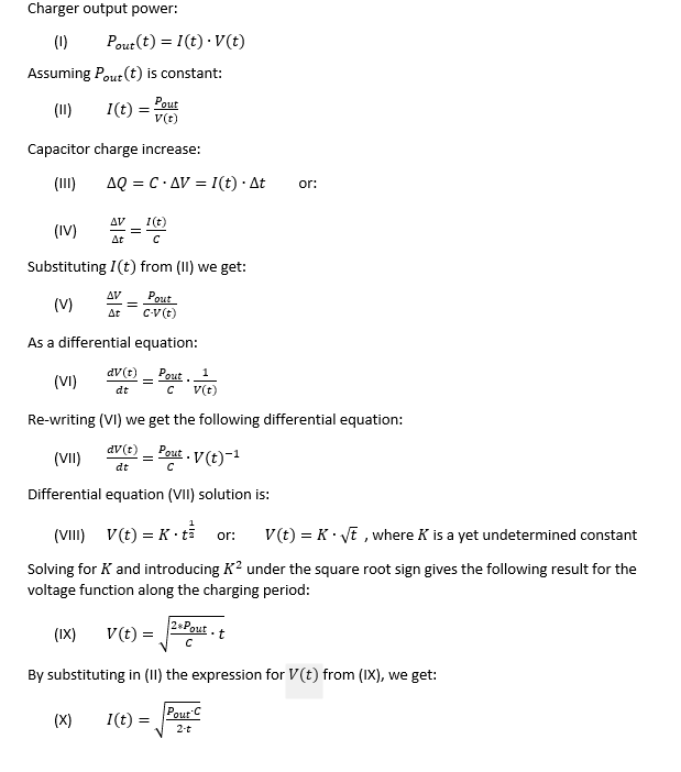
From (IX) we learn that if we could charge a capacitor while delivering constant power, the voltage across it would grow proportionally to the square root of the elapsed time.
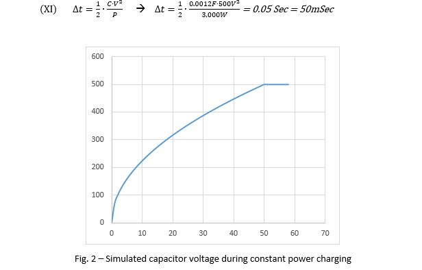
This is shown in figure 2 below, depicting a simulation of the voltage across a 1,200uF capacitor being charged to 500V at a constant power of 3,000Joul/S (or 3,000W). The vertical (voltage) axis is in Volts and the horizontal (time) axis is in mSec. The charging time obtained in the simulation is 50mSec, which is in line with the following calculated charging time obtained by dividing the energy stored in the capacitor by the power delivered to it:
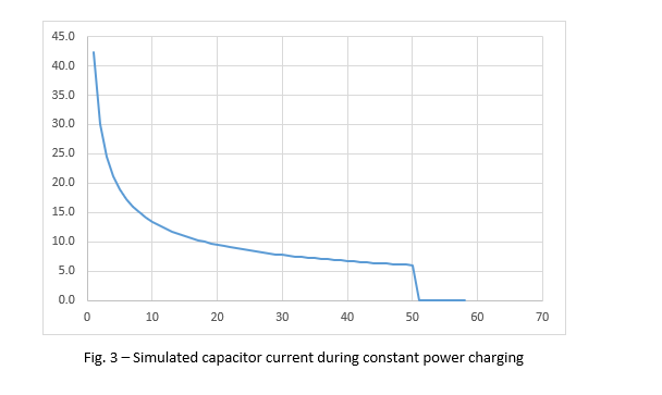
From (X) we learn that if we could charge a capacitor with constant power, the current at the beginning of the charging process (at ) would be infinite, decreasing with time.
Figure 3 below shows the results of a simulation of the current delivered to the capacitor (in Amps) while being charged at constant power (horizontal axis in mSec.). At the first moment (first millisecond not depicted) the current is infinite, and it decreases steadily until the capacitor is fully charged. Once the capacitor is charged the current drops to zero (after 50mSec) and its voltage remains constant.
The practical solution for optimal utilization of the power hardware of the charging power supply would be to start charging the capacitor at maximum constant current until reaching the capacitor charger maximum output power, then keep charging the capacitor at constant power till the desired voltage across the capacitor is reached.
This process is depicted in figure 4 below, which shows the simulation results of the voltage across the capacitor when charged by a quasi-constant power (QCP) capacitor charging power supply (vertical axis in Volts, horizontal axis in mSec.). The simulation parameters are:
- Capacitor value: 1,200uF
- Voltage at end of charge: 500V
- Charger current limit: 22A
- Constant power delivered: 3,250W
During the first 7mS the charging current is limited to 22A showing a linear voltage increase, and then the charging power delivered to the capacitor remains constant (at 3,250W) until full charge is achieved (at 500V).
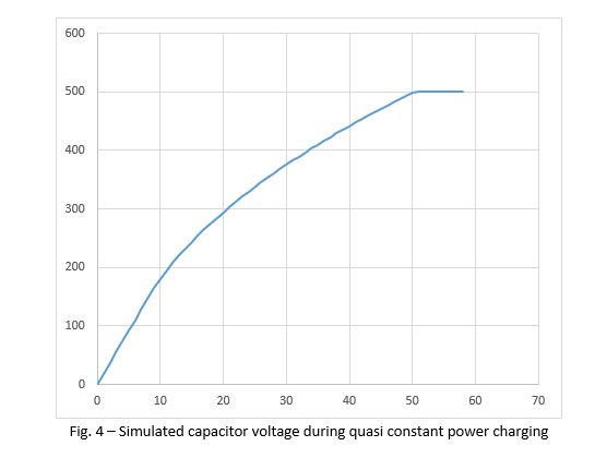
Figure 5 below shows the charging current delivered by the QCP capacitor charging power supply to the capacitor during the charging period (vertical axis in Amps, horizontal axis in mSec.). During the first 7mS the charging current is limited to 22A, decreasing during the charging process.
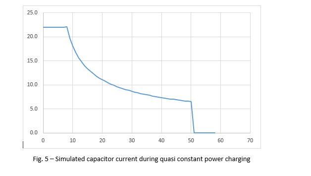
Figure 6 below shows how the output power increases linearly (during the constant current charging period) from zero to full power during the first 7mS until full power (3,250W) is achieved, then the output power remains constant till the capacitor voltage reaches the desired voltage (500V) – and then it drops to zero after 50mS of charging (vertical axis in Watts, horizontal axis in mSec.).
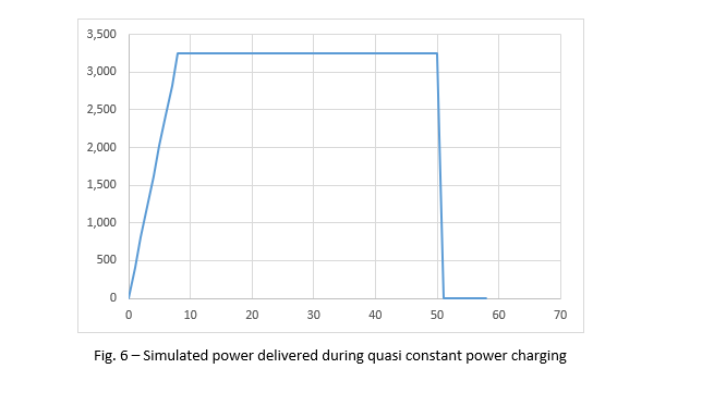
Figure 7 below shows an oscillogram of the voltage across the capacitor recorded during the charging period, obtained with a real QCP capacitor charging power supply (Advice Electronics, Model LCH-3000-500). The oscillogram in figure 7 was recorded with an oscilloscope Agilent DSO7014B.
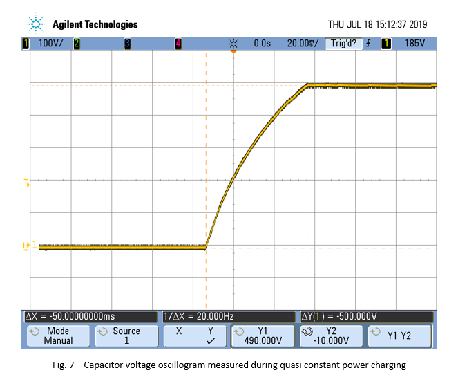
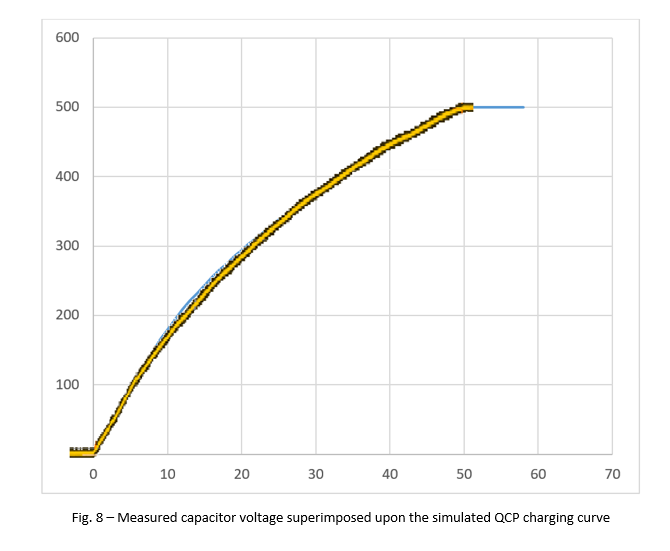
The measured result shown in figure 7 (capacitor charged from zero to 500V in 50mS) compares very well with the theoretical, simulated charging curve shown in figure 4: they are almost identical with a minor deviation during the period between 8mS and 22mS, as can be seen in figure 8 below, in which the measured capacitor voltage (in yellow, as previously shown in figure 7) is properly scaled and superimposed upon the simulated quasi constant power (QCP) charging curve (in blue, as previously shown in figure 4).
Comparing the two approaches on a practical basis
In order to charge a 1,200uF capacitor to 500V in 50mS, a constant current capacitor charging power supply needs to deliver a peak power of 6KW (as shown in figure 1), while a QCP capacitor charging power supply needs to supply a peak power of 3.25KW for achieving the same result.
Form the above discussion we learn that a QCP capacitor charging power supply must deliver a peak power equal to only 108% of the average required output power. A constant current capacitor charging power supply must deliver a peak power equal to 200% of the average required output power, roughly twice the peak power required from a QCP capacitor charging power supply.
This factor has a significant impact on the capacitor charging power supply design, size, reliability and cost.
We conclude that an effective quasi-constant-power (QCP) capacitor charging power supply approach requires from its power components considerably reduced stress and smaller size, resulting also in reduced cost and increased reliability, while operating at a significantly lower peak power than a constant current unit.
This results in a smaller size, more reliable and cost-effective capacitor charging power supply, like the LCH-XXX capacitor charging power supplies series from Advice Electronics Ltd.
