
Introduction
Our thirst for high speed mobile data is insatiable. As we saturate the available RF spectrum in dense urban
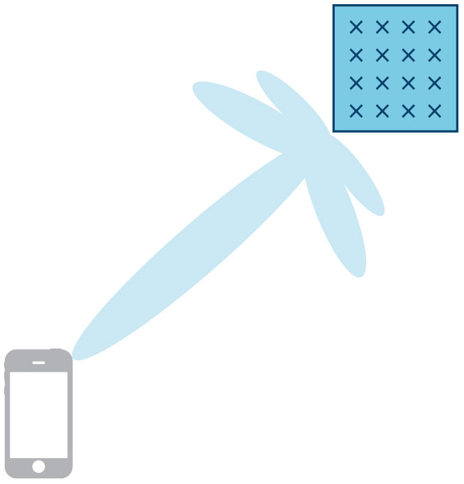
Figure 1. Traditional beamforming.
environments, it’s becoming apparent that there’s a need to increase the efficiency of how we transmitt and receive data from wireless base stations.
Base stations consisting of large numbers of antennas that simultaneously communicate with multiple spatially separated user terminals over the same frequency resource and exploit multipath propagation are one option to achieve this efficiency saving. This technology is often referred to as massive MIMO (multiple-input, multiple-output). You may have heard massive MIMO described as beamforming with a large number of antennas. But this raises the question … what is beamforming?
Beamforming vs. Massive MIMO
Beamforming is a word that means different things to different people. Beamforming is the ability to adapt the radiation pattern of the antenna array to a particular scenario. In the cellular communications space, many people think of beamforming as steering a lobe of power in a particular direction toward a user, as shown in Figure 1. Relative amplitude and phase shifts are applied to each antenna element to allow for the output signals from the antenna array to coherently add together for a particular transmit/receive angle and destructively cancel each other out for other signals. The spatial environment that the array and user are in is not generally considered. This is indeed beamforming, but is just one specific implementation of it.
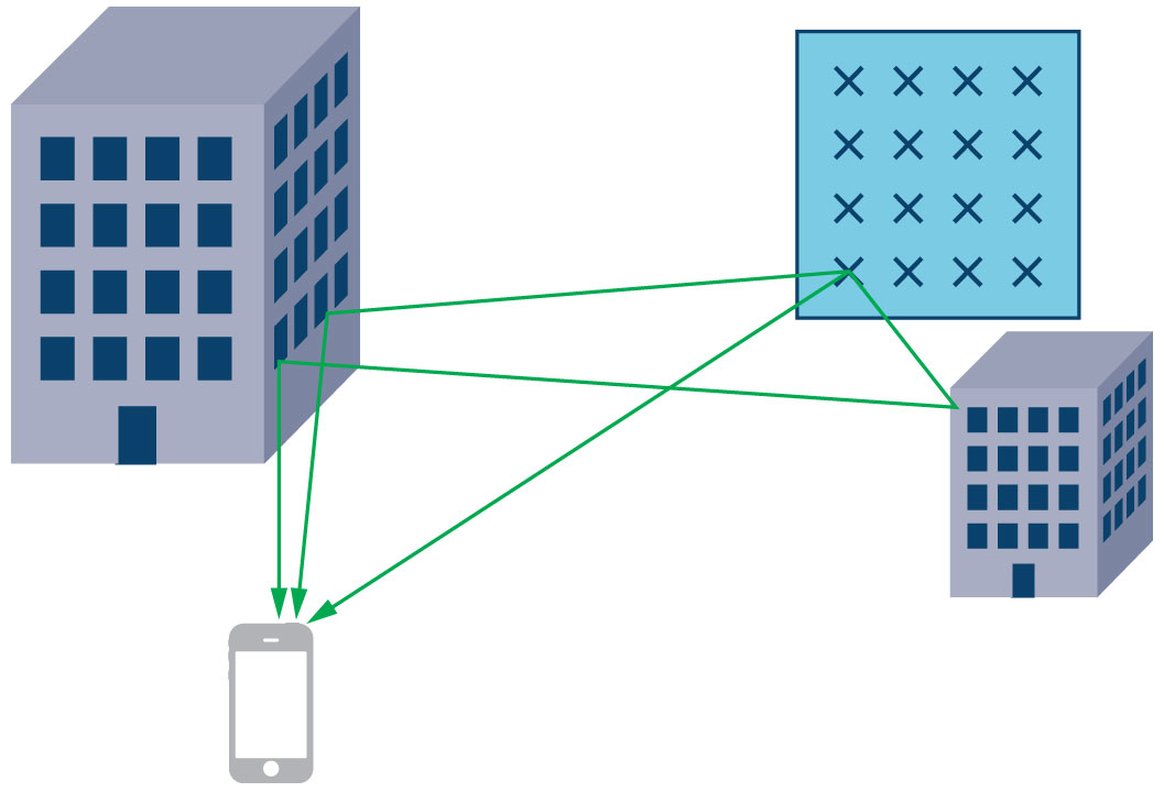
Figure 2. Multipath environment between antenna array and user.
Massive MIMO can be considered as a form of beamforming in the more general sense of the term, but is quite removed from the traditional form. Massive simply refers to the large number of antennas in the base station antenna array. MIMO refers to the fact that multiple spatially separated users are catered for by the antenna array in the same time and frequency resource. Massive MIMO also acknowledges that in real-world systems, data transmitted between an antenna and a user terminal—and vice versa—undergoes filtering from the surrounding environment. The signal may be reflected off buildings and other obstacles, and these reflections will have an associated delay, attenuation, and direction of arrival, as shown in Figure 2. There may not even be a direct line of sight between the antenna and the user terminal. It turns out that these nondirect transmission paths can be harnessed as a power for good.
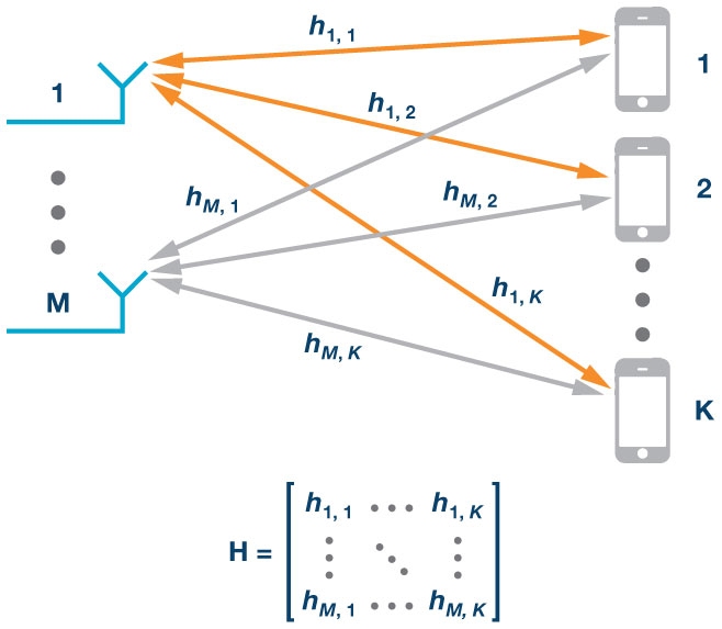
Figure 3. Channel state information needed to characterize a massive MIMO system.
In order to take advantage of the multiple paths, the spatial channel between antenna elements and user terminals needs to be characterized. In literature, this response is generally referred to as channel state information (CSI). This CSI is effectively a collection of the spatial transfer functions between each antenna and each user terminal. This spatial information is gathered in a matrix (H), as shown in Figure 3. The next section looks at the concept of CSI and how it is collected in more detail. The CSI is used to digitally encode and decode the data transmitted from and received by the antenna array.
Characterizing the Spatial Channel Between Base Station and User
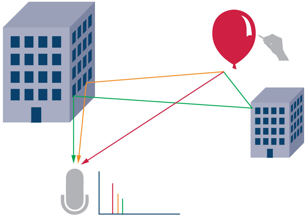
Figure 4. Audio analogy to demonstrate spatial characterization of a channel.
An interesting analogy is to consider a balloon being popped at one location and the sound of this pop, or impulse, being recorded at another, as shown in Figure 4. The sound recorded at the microphone position is a spatial impulse response that contains information unique to the particular position of both the balloon and the microphone in the surrounding environment. The sound that is reflected off obstacles is attenuated and delayed compared to the direct path.

Figure 5. Audio analogy to downlink channel characterization.
If we expand the analogy to compare to the antenna array/user terminal case, we need more balloons, as seen in Figure 5. Note that in order to characterize the channel between each balloon and the microphone, we need to burst each balloon at a separate time so the microphone doesn’t record the reflections for different balloons overlapping. The other direction also needs to be characterized, as shown in Figure 6. In this instance, all the recordings can be done simultaneously when the balloon is popped at the user terminal position. This is clearly a lot less time consuming!

Figure 6. Audio analogy to uplink channel characterization.
In the RF space, pilot signals are used for characterizing the spatial channels. The over-the-air transmission channels between antennas and user terminals are reciprocal, meaning the channel is the same in both directions. This is contingent on the system operating in time division duplex (TDD) mode as opposed to frequency division duplex (FDD) mode. In TDD mode, uplink and downlink transmissions use the same frequency resource. The reciprocity assumption means the channel only needs to be characterized in one direction. The uplink channel is the obvious choice, as just one pilot signal needs to be sent from the user terminal and is received by all antenna elements. The complexity of the channel estimation is proportional to the number of user terminals, not the number of antennas in the array. This is of critical importance given the user terminals may be moving, and hence the channel estimation will need to be performed frequently. Another significant advantage of uplink-based characterization means that all the heavy duty channel estimation and signal processing is done at the base station, and not at the user end.

Figure 7. Each user terminal transmits orthogonal pilot symbol.
So now that the concept of collecting CSI has been established, how is this information applied to data signals to allow for spatial multiplexing? Filtering is designed based on the CSI to precode the data transmitted from the antenna array so that multipath signals will coherently add at the user terminals position. Such filtering can also be used to linearly combine the data received by the antenna array RF paths so that the data streams from different users can be detected. The following section addresses this in more detail.
The Signal Processing that Enables Massive MIMO
In the previous section we’ve described how the CSI (denoted by the matrix H) is estimated. Detection and precoding matrices are calculated based on H. There are a number of methods for calculating these matrices. This article focuses on linear schemes. Examples of linear precoding/detection methods are maximum ratio (MR), zero forcing (ZF), and minimum mean- square error (MMSE). Full derivations of the precoding/detection filters from the CSI are not provided in this article, but the criteria they optimize for, as well as the advantages and disadvantages of each method are discussed. A more detailed treatment of these topics can be found in the references at the end of this article.1, 2, 3
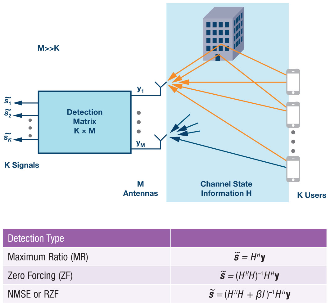
Figure 8. Uplink signal processing. H denotes the conjugate transpose.
Figure 8 and Figure 9 give a description of how the signal processing works in the uplink and downlink respectively for the three linear methods previously mentioned. For precoding there may also be some scaling matrix to normalize the power across the array that has been omitted for simplicity.
Maximum ratio filtering, as the name suggests, aims to maximize the signal-to-noise ratio (SNR). It is the simplest approach from a
signal processing viewpoint, as the detection/precoding matrix is just the conjugate
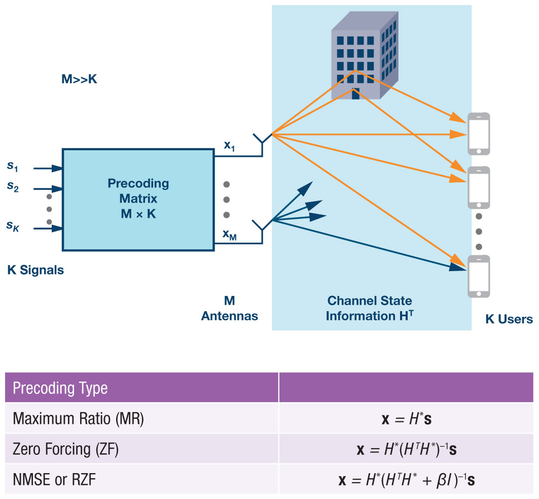
Figure 9. Downlink signal processing. T denotes the transpose. * denotes the conjugate.
transpose or conjugate of the CSI matrix, H. The big downside of this method is that inter user interference is ignored.
Zero forcing precoding attempts to address the inter user interference problem by designing the optimization criteria to minimize for it. The detection/precoding matrix is the pseudoinverse of the CSI matrix. Calculating the pseudoinverse is more computationally expensive than the complex conjugate as in the MR case. However, by focusing so intently on minimizing the interference, the received power at the user suffers.
MMSE tries to strike a balance between getting the most signal amplification and reducing the interference. This holistic view comes with signal processing complexity as a price tag. The MMSE approach introduces a regularization term to the optimization—denoted as β in Figures 8 and 9—that allows for a balance to be found between the noise covariance and the transmit power. It is sometimes also referred to in literature as regularized zero forcing (RZF).
This is not an exhaustive list of precoding/detection techniques, but gives an overview of the main linear approaches. There are also nonlinear signal processing techniques such as dirty paper coding and successive interference cancellation that can be applied to this problem. These offer optimal capacity but are very complex to implement. The linear approaches described above are generally sufficient for massive MIMO, where the number of antennas gets large. The choice of a precoding/detection technique will depend on the computational resources, the number of antennas, the number of users, and the diversity of the particular environment the system is in. For large antenna arrays where the number of antennas is significantly greater than the number of users, the maximum ratio approach may well be sufficient.
The Practical Obstacles Real-World Systems Present to Massive MIMO
When massive MIMO is implemented in a real-world scenario, there are further practical considerations to be taken into account. Consider an antenna array with 32 transmit (Tx) and 32 receive (Rx) channels operating in the 3.5 GHz band as an example. There are 64 RF signal chains to be put in place and the spacing between the antennas is approximately 4.2 cm given the operating frequency. That’s a lot of hardware to pack into a small space. It also means there is a lot of power being dissipated, which brings inevitable temperature concerns. Analog Devices’ integrated transceivers offer a highly effective solution to many of these issues. The AD9371 will be discussed in more detail in the next section.
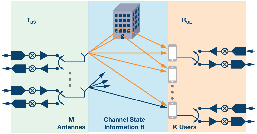
Figure 10. Real-world downlink channel.
Previously in this article, the application of reciprocity to the system to drastically cut the channel estimation and signal processing overheads were discussed. Figure 10 shows the downlink channel in a real-world system. It is split into three components; the over-the-air channel (H), the hardware response of the base station transmit RF paths (TBS), and the hardware response of the user receive RF paths (RUE). The uplink is the opposite of this with RBS characterizing the base station receive hardware RF paths and TUE characterizing the users transmit hardware RF paths. While the reciprocity assumption holds for the over the air interface, it does not for the hardware paths. The RF signal chains introduce inaccuracies into the system due to mismatched traces, poor synchronization between the RF paths, and temperature-related phase drift.
Using a common synchronized reference clock for all LO (local oscillator) PLLs in the RF paths and synchronized SYSREFs for the baseband digital JESD204B signals will help address latency concerns between the RF paths. However, there will still be some arbitrary phase mismatch between the RF paths at system startup. Temperature-related phase drift contributes further to this issue and it is clear that calibration is required in the field when the system is initialized and periodically thereafter. Calibration allows for the advantages of reciprocity such as maintaining the signal processing complexity at the base station and uplink only channel characterization to be kept. It can generally be simplified so that only the base station RF paths (TBS and RBS) need to be considered.
There are a number of approaches to calibrating these systems. One is to use a reference antenna positioned carefully in front of the antenna array to calibrate both the receive and transmit RF channels. It’s questionable whether having an antenna placed in front of the array in this way is suited to practical base station calibration in the field. Another is to use mutual coupling between the existing antennas in the array as the calibration mechanism. This may well be feasible. The most straight forward approach is probably to add passive coupling paths just before the antennas in the base station. This adds more complexity in the hardware domain, but should provide a robust calibration mechanism. To fully calibrate the system a signal is sent from one designated calibration transmit channel, which is received by all RF receive paths through the passive coupled connection. Each transmit RF path then sends a signal in sequence that is picked up at the passive coupling point before each antenna, relayed back to a combiner, and then to a designated calibration receive path. Temperature related effects are generally slow to change, so this calibration does not have to be performed very frequently, unlike the channel characterization.
Analog Devices’ Transceivers and Massive MIMO Analog Devices’ range of integrated transceiver products are particularly suited to applications where there is a high density of RF signal chains required. AD9371 features 2 transmit paths, 2 receive paths, and an observation receiver, as well as three fractional-N PLLs for RF LO generation in a 12 mm × 12 mm package. This unrivaled level of integration enables manufacturers to create complex systems in a timely and cost-effective manner.
A possible system implementation featuring multiple AD9371 transceivers is shown in Figure 11. This is a 32 transmit, 32 receive system with 16 AD9371 transceivers. Three AD9528 clock generators provide the PLL reference clocks and JESD204B SYSREFs to the system. The AD9528 is a 2-stage PLL with 14 LVDS/HSTL outputs and an integrated JESD204B SYSREF generator for multiple device synchronization. The AD9528s are arranged in a fanout buffer configuration with one acting as a master device with some of its outputs used to drive the clock inputs and the SYSREF inputs of the slave devices. A possible passive calibration mechanism is included—shown in green and orange—where a dedicated transmit and receive channel are used to calibrate all the receive and transmit signal paths through a splitter/combiner, as discussed in the previous section.
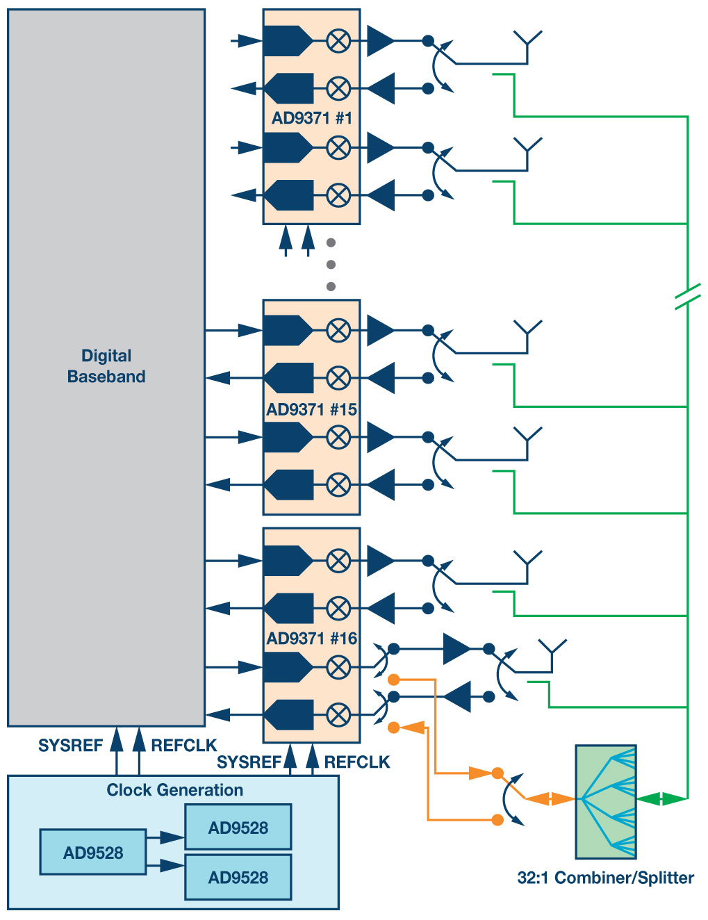
Figure 11. Block diagram of 32 Tx, 32 Rx massive MIMO radio head featuring Analog Devices’ AD9371 transceivers.
Conclusion
Massive MIMO spatial multiplexing has the potential to become a game changing technology in the cellular communications space, allowing for increased cellular capacity and efficiency in high traffic urban areas. The diversity that multipath propagation introduces is exploited to allow for data transfer between a base station and multiple users in the same time and frequency resource. Due to reciprocity of the channel between the base station antennas and the users, all the signal processing complexity can be kept at the base station, and the channel characterization can be done in the uplink. Analog Devices’ RadioVerse™ family of integrated transceiver products allow for a high density of RF paths in a small space, so they are well suited to massive MIMO applications.
References
- Xiang Gao. Massive MIMO in Real Propagation Environments. Lund University, 2016.
- Michael Joham, Josef A. Nossek, and Wolfgang Utschick. “Linear Transmit Processing in MIMO Communications Systems.” IEEE Transactions on Signal Processing, Vol. 53, Issue 8, Aug, 2005.
- Hien Quoc Ngo. Massive MIMO: Fundamentals and System Design. Linköping University, 2015.
Claire Masterson
[claire.masterson@analog.com] is a systems applications engineer in the Communication Systems Team at Analog Devices Limerick working on systems implementation, software development, and algorithm development. Claire received a BAI and PhD from Trinity College in Dublin and joined ADI in 2011 after graduating.