

The discovery of X-radiation by Wilhelm Conrad Röntgen in 1895 earned him the first Nobel Prize in Physics and laid the historical foundations for the field of medical imaging. Since then it has developed into an extensive scientific discipline that, in its widest sense, designates diverse techniques for noninvasive visualization of the internal aspects of the body.
This article considers the main types of modern medical imaging systems that utilize fundamentally different physical principles and processing techniques but have one thing in common—an analog data acquisition front end serving for signal conditioning and conversion of raw imaging data into a digital domain.
This tiny functional front-end block is hidden deep inside a complex machine. However, it is its performance that has a crucial impact on the resulting image quality of the complete system. Its signal chain comprises a sensing element, a low noise amplifier (LNA), a filter, and an analog-to-digital converter (ADC), of which the latter is the main subject of this article.
The data converter constitutes the most demanding challenges imposed by medical imaging on the electronics design in terms of required dynamic range, resolution, accuracy, linearity, and noise. This article discusses these design challenges in the context of different imaging modalities and gives an overview of advanced data converters and integrated solutions needed to make them work at optimum levels.
Digital Radiography
Digital radiography (DR) is based on physical principles common to all conventional absorption-based radiography systems. The X-rays passing through the body are attenuated by tissues of different radiographic opacity and projected on a flat panel detector system, as shown schematically in Figure 1. The detector converts the X-ray photons into electrical charges that are proportional to the energy of the incident particles. The resulting electrical signal is amplified and converted into a digital domain to produce an accurate digital representation of the X-ray image. The quality of this image depends on the signal sampling in the spatial and intensity dimensions.
In the spatial dimension, the minimum sampling rate is defined by the pixel matrix size of the detector and the update rate for real-time fluoroscopy imaging. Flat panel detectors with millions of pixels and typical update rates as high as 25 fps to 30 fps employ channel multiplexing and multiple ADCs with sampling rates up to several dozens of MSPS to meet the minimum conversion time without sacrificing accuracy.
In the intensity dimension, the digital output signal of an ADC represents the integrated amount of X-ray photons absorbed in a given pixel over a specific exposure time. This value is binned into a finite number of discrete levels defined by the bit-depth of an ADC. The signal-to-noise ratio (SNR) is another important parameter that defines the intrinsic ability of the system to faithfully represent the anatomic features of the imaged body. Digital X-ray systems use 14-bit to 18-bit ADCs with SNR levels ranging from 70 dB up to 100 dB depending on the type of the imaging system and its requirements. There are a wide range of discrete ADCs and integrated analog front ends to enable various types of DR imaging systems with increased dynamic range, finer resolution, higher detection efficiency, and lower noise.
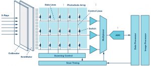
Figure 1. Digital X-ray detector signal chain.
Computed Tomography
Computed tomography (CT) also uses ionizing radiation but, unlike digital X-ray technology, it is based on an arc-shaped detector system synchronously rotating with an X-ray source and utilizes more sophisticated processing techniques to produce high resolution 3D images of blood vessels, soft tissue, and more.
The CT detector is the central component of the entire system architecture and, indeed, is the heart of the CT system. It is comprised of multiple modules, which are depicted in Figure 2. Each module transforms the incident X-rays into electrical signals routed into the multichannel analog Data acquisition system (ADAS). Each module contains a scintillating crystal array, a photodiode array, and the ADAS, which contains multiple integrator channels that are multiplexed into the ADCs. The ADAS must have very low noise performance to maintain good spatial resolution with reduced X-ray dosage and to achieve high dynamic range performance with extremely low current outputs. To avoid image artifacts and ensure good contrast, the converter front end must have highly linear performance and offer low power operation to relax cooling requirements for the temperature sensitive detector.
The ADC must have high resolution of at least 24 bits to achieve better and sharper images, and a fast sampling rate to digitize detector readings that can be as short as 100 µs. The ADC sampling rate must also enable multiplexing, which would allow the use of fewer converters as well as the reduction of the size and power of the entire system.
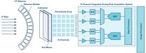
Figure 2. CT detector module signal chain.
Positron Emission Tomography
Positron emission tomography (PET) involves ionizing radiation resulting from a radionuclide introduced into a human body. It emits positrons that collide with electrons in tissue, generating pairs of gamma rays radiated roughly in opposite directions. These pairs of high energy photons simultaneously strike opposing PET detectors aligned in a ring around a gantry bore.
The PET detector, schematically shown in Figure 3, consists of an array of scintillators and photomultiplier tubes (PMTs) converting gamma rays into electrical currents that are translated into voltages, and then amplified and compensated for amplitude variations by using variable gain amplifiers (VGAs). The resulting signal is split between ADC and comparator paths to provide energy and timing information used by the PET coincidence processor to reconstruct a 3D image of a radioactive tracer concentration within the body.
Two photons can be classified as relevant if their energies are around 511 keV and if their detection times differ by less than one ten-billionth of a second. The photons’ energy and the detection time difference impose strict requirements on the ADC, which must have good resolution of 10 to 12 bits and fast sampling rates typically better than 40 MSPS. Low noise performance to maximize the dynamic range and low power operation to reduce heat dissipation are also important for PET imaging.
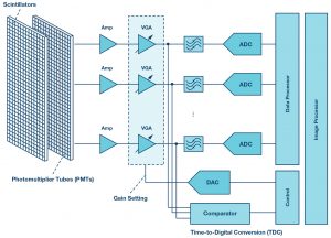
Figure 3. PET electronic front-end signal chain.
Magnetic Resonance Imaging
Magnetic resonance imaging (MRI) is a noninvasive medical imaging technique that relies on the phenomenon of nuclear magnetic resonance and does not use ionizing radiation, which distinguishes it from DR, CT, and PET systems.
The carrier frequencies of the MR signals scale directly with the main magnetic field strength, with the frequencies ranging in commercial scanners from 12.8 MHz to 298.2 MHz. Signal bandwidth is defined by the field-of-view in the frequency-encoding direction and can vary from a few to several dozens of kHz.
This imposes specific requirements on the receiver front end, which is typically based on a superheterodyne architecture (see Figure 4) with lower speed SAR ADCs. However, recent advancements in analog-to-digital conversion enabled fast and low power multichannel pipeline ADCs for direct digital conversion of the MR signals in the most common frequency ranges at conversion rates exceeding 100 MSPS at a 16-bit depth. The requirement for dynamic range is very demanding—it typically exceeds 100 dB. Enhanced image quality is achieved by oversampling the MR signal, which improves resolution, increases SNR, and eliminates aliasing artifacts in the frequency-encode direction. For fast scan acquisition times, the compressed sensing technique based on undersampling is applied.
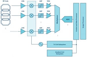
Figure 4. MRI superheterodyne receiver signal chain.
Ultrasonography
Ultrasonography or medical ultrasound is based on a physical principle different from all other imaging modalities discussed in this article. It utilizes pulses of acoustic waves in the frequency range from 1 MHz to 18 MHz. These waves screen the internal body tissue and reflect them back as echoes of varying intensity. These echoes are acquired and displayed in real-time as a sonogram that may contain different types of information, including the acoustic impedance, blood flow, motion of tissue over time, or its stiffness.
The key functional block of the medical ultrasound front end shown in Figure 5 is represented by an integrated multichannel analog front end (AFE) that includes a low noise amplifier, a variable-gain amplifier, an antialiasing filter (AAF), an ADC, and demodulators. One of the most important requirements imposed on the AFE is the dynamic range. Depending on the imaging mode, this requirement can demand 70 dB to 160 dB to distinguish between blood signals and background noise resulting from probe and body tissue movements. Therefore an ADC must provide high resolution, a high sampling rate, and low total harmonic distortion (THD) to maintain dynamic fidelity of the ultrasound signal. Low power dissipation is another important requirement dictated by the high channel density of the ultrasound front end. There are a range of integrated AFEs for medical ultrasound equipment to enable the best image quality, reduced power consumption, and smaller system size and cost.
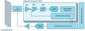
Figure 5. Medical ultrasound front-end signal chain.
Conclusion
Medical imaging imposes most demanding requirements on the electronic design. Low power, low noise, high dynamic range, and high resolution performance at low cost and in a compact package are common trends dictated by the requirements of the modern medical imaging systems discussed in this article. Analog Devices addresses these requirements and offers highly integrated solutions for the key signal chain functional blocks to enable best-in-class clinical imaging equipment that is increasingly becoming an integral part of international healthcare systems today. Here is a list of products ideal for the various medical imaging modalities mentioned in this article.
- ADAS1256: This highly integrated analog front end incorporates 256 channels with low noise integrators, low-pass filters, and correlated double samplers that are multiplexed into a high speed, 16-bit ADC. It is a complete charge-to-digital conversion solution designed for DR applications that can be directly mounted on a digital X-ray panel.
- For discrete DR systems, the 18-bit PulSAR® ADC AD7960 offers 99 dB of SNR and a 5 MSPS sampling rate to deliver unmatched performance to meet requirements for the highest dynamic range both in noise and in The 16-bit, dual-channel AD9269 and 14-bit, 16-channel AD9249 pipeline ADCs offer sampling rates of up to 80 MSPS and 65 MSPS, respectively, to enable high speed fluoroscopy systems.
- ADAS1135 and ADAS1134: These highly integrated 256- and 128-channel data acquisition systems are comprised of low noise, low power, low input current integrators, simultaneous sample-and-hold devices, and two high speed ADCs with a configurable sampling rate and resolution of up to 24 bits with excellent linearity performance to maximize image quality for CT applications.
- AD9228, AD9637, AD9219, and AD9212: These 12- and 10-bit multichannel ADCs with sampling rates from 40 MSPS to 80 MSPS are optimized for outstanding dynamic performance and low power to meet PET requirements.
- AD9656: This 16-bit quad pipeline ADC offers a conversion rate up to 125 MSPS and is optimized for outstanding dynamic and low power performance for conventional and direct digital conversion MRI system architectures.
- AD9671: This 8-channel integrated receiver front end is designed for low cost and low power medical ultrasound applications featuring a 14-bit ADC with up to 125 Each channel is optimized for a high dynamic performance of 160 dBFS/√Hz and low power of 62.5 mW in continuous wave mode for applications where a small package size is critical.
Anton Patyuchenko [anton.patyuchenko@analog.com] received his Master of Science in microwave engineering from the Technical University of Munich in 2007. Following his graduation, Anton worked as a scientist at German Aerospace Center (DLR). He joined Analog Devices as a field applications engineer in 2015 and is currently providing field applications support to strategic and key customers of Analog Devices specializing in healthcare, energy, and microwave applications.
