Today, engineers and technicians typically experience multiple cable testing challenges in the field. Keysight Technologies recently introduced two innovative measurement options that make its FieldFox handheld analyzers the industry’s most comprehensive and effective cable test solution to meet these challenges head on.
Common Cable Test Challenges
Cables (e.g., waveguide, coaxial and twisted-pair) are by far the most widely used components in modern RF and microwave systems like wireless and data communication, satellite communications and RADAR. They are also the leading cause of failure in these types of systems. That’s why their proper maintenance and using the right tool for testing in the field is so critical.
The typical cable test process starts by determining whether or not a cable is faulty or performing outside the desired specification. If it is, the failure’s physical location along the cable must then be located. Once the location is determined, the next step is to understand what the error is and repair it. During troubleshooting and maintenance, engineers and technicians can identify a fault’s location with Return Loss (RL) and Distance-to-Fault (DTF) methods, but they are unable to determine the cause or type of fault, making it difficult to repair. In many cases, the failures (e.g., loose or damaged connectors, water ingress or broken solder joints) can’t be seen by just looking at the cable.
Also problematic is that measuring cable performance has traditionally required engineers and technicians to transport a cable and antenna analyzer, network analyzer, signal generator, and power meter into the field. That process is all the more complicated when the cables are used in systems located in hard to reach or even potentially hazardous environments. Once in place, the instruments would need to be correctly set up for testing. While effective, the process is error prone and leaves the instruments subject to accidental damage.
Further complicating matters, traditional vector network analyzers (VNAs) have difficulty making precise and repeatable high-loss measurements for in-situ microwave cables where test ports are long distances apart.
Easier Cable Measurements with FieldFox’s Enhanced Cable Test Suite
FieldFox’s new Time Domain Reflectometry (TDR) cable measurement option (Option 215) complements the analyzer’s current RL and DTF measurements. The RL measurement capability exposes mismatch of cable connections, while the DTF capability indicates the location of any faults or poor connections along the cable. The new TDR option provides engineers with new insight to help measure the impedance changes along the cable and identify the cause (type) of specific faults, such as short, open or water ingress. To date, FieldFox is the only handheld analyzer than can perform RL, DTF and TDR measurements in the same instrument.
FieldFox’s TDR or step measurement captures data using the same process as DTF. However, unlike DTF, the measurement is used to characterize the type of fault, including inductive or capacitive discontinuities. It does so by observing reflected waveforms from a step propagating through a cable. By analyzing the duration, magnitude and shape of the reflections, the nature of the impedance variation in the cable can be determined. FieldFox’s TDR measurement mode is only useful for cables that operate down to DC (e.g., two-conductor transmission lines).
When measuring a waveguide, FieldFox utilizes a bandpass time-domain transform technique. This is necessary because of the waveguide’s narrowband response, which restricts the type of time-domain measurements that can be made. The bandpass measurement is ideal for frequency limited DUTs; however, it only provides the location of the fault. Determining the type of discontinuity, such as inductive, capacitive or resistive, is not possible.
Another new FieldFox option, Extended Range Transmission Analysis (ERTA, Option 209), helps overcome the challenges of measuring long microwave cables in the field. This portable solution measures scalar insertion loss of in-situ microwave cables with long distances between test ports, and makes it possible to access both ends of the cable or waveguide simultaneously.
Using a scalar analyzer as the signal source with a broadband detector or power sensor to measure cable loss can also be a slow process; one that is prone to external interference and does not offer high levels of dynamic range. Deploying a benchtop solution in the field is also non-ideal due to its large size and cost.
With ERTA, two FieldFox analyzers are deployed at each end of the measured cable. One analyzer acts as a source, while the other acts as a receiver. Both instruments are step synchronized with hardware triggers. By taking advantage of Keysight’s proprietary InstAlign spectrum analysis technique, engineers and technicians can use this configuration to make very accurate cable loss measurements without calibration and warm up (Figure 1). It also offers industry’s best dynamic range for long, lossy cable measurement. This option can also be configured with frequency-offset to measure devices such as mixers and converters.
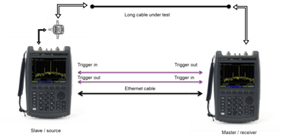
Figure 1. FieldFox can be easily upgraded with the new ERTA Option to make highly accurate cable loss measurements.
FieldFox: Offering the Most Comprehensive Handheld Test Suite
In addition to FieldFox’s new TDR and ERTA options, the analyzer provides a number of additional measurements; all of which give FieldFox the most comprehensive test suite in a single handheld instrument (Figure 2). These additional measurements include:
- RL, VSWR, and DTF for broadband and band-pass cable subsystems
- S-parameter, group delay, phase, Smith chart, and time-domain analysis
- Frequency converter conversion gain/loss
- Mixed-mode, 1-port S-parameter, time-domain analysis
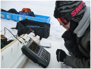
Figure 2. FieldFox provides the industry’s most comprehensive handheld cable test solution that is precise enough for the lab and rugged enough for the field.
Real-World Examples
To better understand how FieldFox’s time-domain measurement techniques help identify the location and cause of cable faults, consider the example of two short 50-ohm coaxial cables connected together with a coaxial adapter. The shorter cable is connected to port 1 on FieldFox, while the second cable is terminated in a 50-ohm load. As shown in Figure 3, a DTF measurement of the cables is very helpful in locating any discontinuities.
Notice that markers are placed at the three peaks in the measured DTF response. The peaks represent the magnitude of single reflections from a discontinuity. Marker 1, which represents the interface between the calibrated FieldFox and the first coaxial cable, reports a distance of 0 meters. Marker 2, located at the adapter between the two cables, reports a distance of 4 meters. It also indicates that the length of the first cable is 4 meters. Marker 3, located at the 50-ohm load, reports a distance of 13.8 meters. With this measurement, the length of the second cable can be calculated (e.g., 13.8 m – 4 m = 9.8 m). The noticeable drop in measured amplitude to the right of the 50-ohm load signifies the end of the cable. As this reflection measurement represents two-way signal paths, FieldFox properly adjusts the marker values and x-axis formatting to the appropriate one-way lengths.
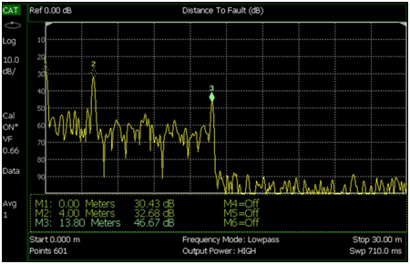
Figure 3. Shown here is a FieldFox DTF measurement for two connected coaxial cables terminated in a 50-ohm load.
Now, consider a coaxial cable that has been damaged in two areas (Figures 4A and 4B). Fault A is a bend in the cable that has exceeded the manufacturer’s specification for minimum bend radius of 1-inch. The bend at Fault A is well below this radius, creating an undesired reflection from this part of the cable. Fault B is a cut through the outer conductor of the cable. The braided shield has been partially removed, exposing the inner dielectric of the coax. Both faults can be examined using the DTF and TDR modes on FieldFox; however, only the TDR measurement will characterize fault type.
Figure 4C shows the measurement for the damaged cable with FieldFox in TDR mode. As can be seen from the TDR response, the cable impedance is generally 50 ohms across most of the time-domain response until a discontinuity is encountered. Discontinuities occur at the input connector, the bend at fault A, the cut at fault B, and the 50-ohm termination at the end.
Of all discontinuities on the cable, the cut at fault B has the largest mismatch. This is demonstrated by the magnitude of the associated peak. The cut on the TDR response has a single peak in the positive direction, indicating an inductive mismatch. This is typical for cuts in the outer conductor of a coaxial cable. Generally speaking, if the cable terminated in a load with a resistance smaller than the characteristic impedance, the TDR response would show a step in the negative direction. If the load resistance were larger than the characteristic impedance, the TDR response would show a step in the positive direction.
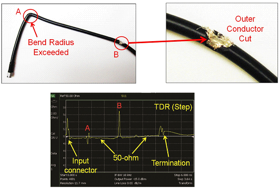
Figure 4. The top left-most and right-most images, A and B, respectively, depict damage in a coaxial cable. The bottom image, 2C, is the result of a TDR measurement of the damaged cable using the FieldFox TDR option. FieldFox can identify various types of discontinuities in TDR mode, including: R > Z0, R < Z0, inductive, and capacitive.
Summary
Cable measurement in the field can be tricky. Determining that a cable is faulty is just the first step in the process. Engineers and technicians then need to identify the fault’s physical location and its cause. This is accomplished using various time-domain techniques. FieldFox’s comprehensive suite of cable test measurements, including the new TDR and ERTA options provide the ideal solution for testing any cable system in the field. FieldFox’s DTF and TDR time-domain measurements identify fault locations and causes in coaxial cables, while its bandpass measurement finds the physical location of faults in a waveguide. Using FieldFox, today’s engineers and technicians now have a faster, easier way to test cable systems in the field.
For more information on transmission line theory or time-domain measurement techniques, check out Keysight’s on-demand cable test webcast (www.keyight.com/find.fieldfoxwebcasts) and the FieldFox Cable Testing Application Note (www.keysight.com/find/fieldfoxapps).
About the Author
Tom Hoppin is an application consultant on contract to Keysight Technologies. Tom started his career as an electronic aviation technician in the U.S. Marine Corps. He joined Hewlett-Packard after his service ended in 1973. Through the years he has held a number of engineering and management roles at HP/Agilent and now Keysight, focused on test system design and spectrum analysis. Tom retired in 2009. He has since returned to Keysight as an application specialist for its RF and Microwave Handheld Analyzers.