
An explanation of how to complete a low-cost design and analysis using a single-phase AC induction motors and an 8bit microcontroller in a garage door application
Small AC induction motors, say for opening garage doors, can have speed control and soft start added with little cost using a three-phase inverter circuit. These permanent split capacitor (PSC) motors are among the simplest and widest used for this type of application. They have low starting torque and current, but can be inefficient due to the non-polarised run capacitor, which often fails before the rest of the motor.
These single-phase motors are often referred to as two-phase motors because they cannot run without sufficient phase shift between the two windings. The capacitor is placed between the input signal and winding to produce an approximate 90˚ phase shift.
The switch is often replaced with a relay that can control the direction by swapping which phase leads or lags the other. The value of the capacitor is typically specified by the motor manufacturer and is sometimes in the range of 5 to 50µF for motors that are less than 0.75kW, of the type being looked at here. The capacitor should be carefully chosen to correct the power factor for maximum power efficiency.
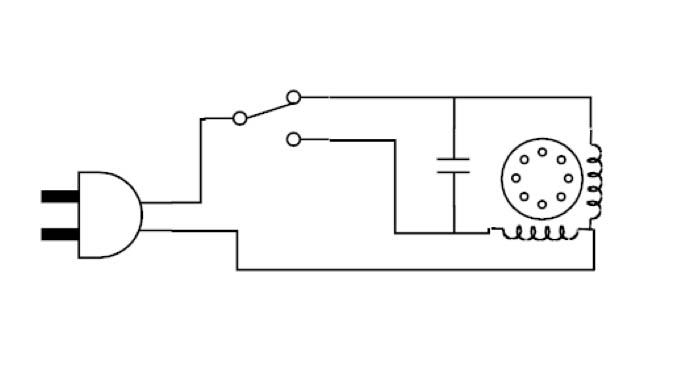
Fig. 1 shows the topology of a traditional AC induction motor.
The voltage rating is typically high at around 220 to 450V, depending on the input voltage. The capacitor must not be polarised, since it is across an alternating voltage. If this capacitor fails, the motor will cease to turn. The importance of selecting the correct capacitor is therefore critical.
A practical capacitor has resistance and radiates heat as it consumes the RMS AC ripple current within its equivalent series resistance. The permanently installed capacitor trades off starting torque capability at standstill with ripple torque reduction at running speed. Because of the high VA rating of the capacitor, it is often selected to meet the minimum starting performance requirements, resulting in poor running efficiency.
For motors that do not have identical windings, it is necessary to feed the two phases with different voltages. This asymmetry is due to the presence of the capacitor, which forms a resonant circuit with the motor’s inductance. Consequently, this raises the voltage across one of the windings and causes uneven current flow.
However, a three-phase inverter can be used to replace the permanent capacitor, as shown in Fig. 2. This allows the speed of the motor to be adjusted with the appropriate amount of voltage applied to each winding so that weaker windings are not overdriven.
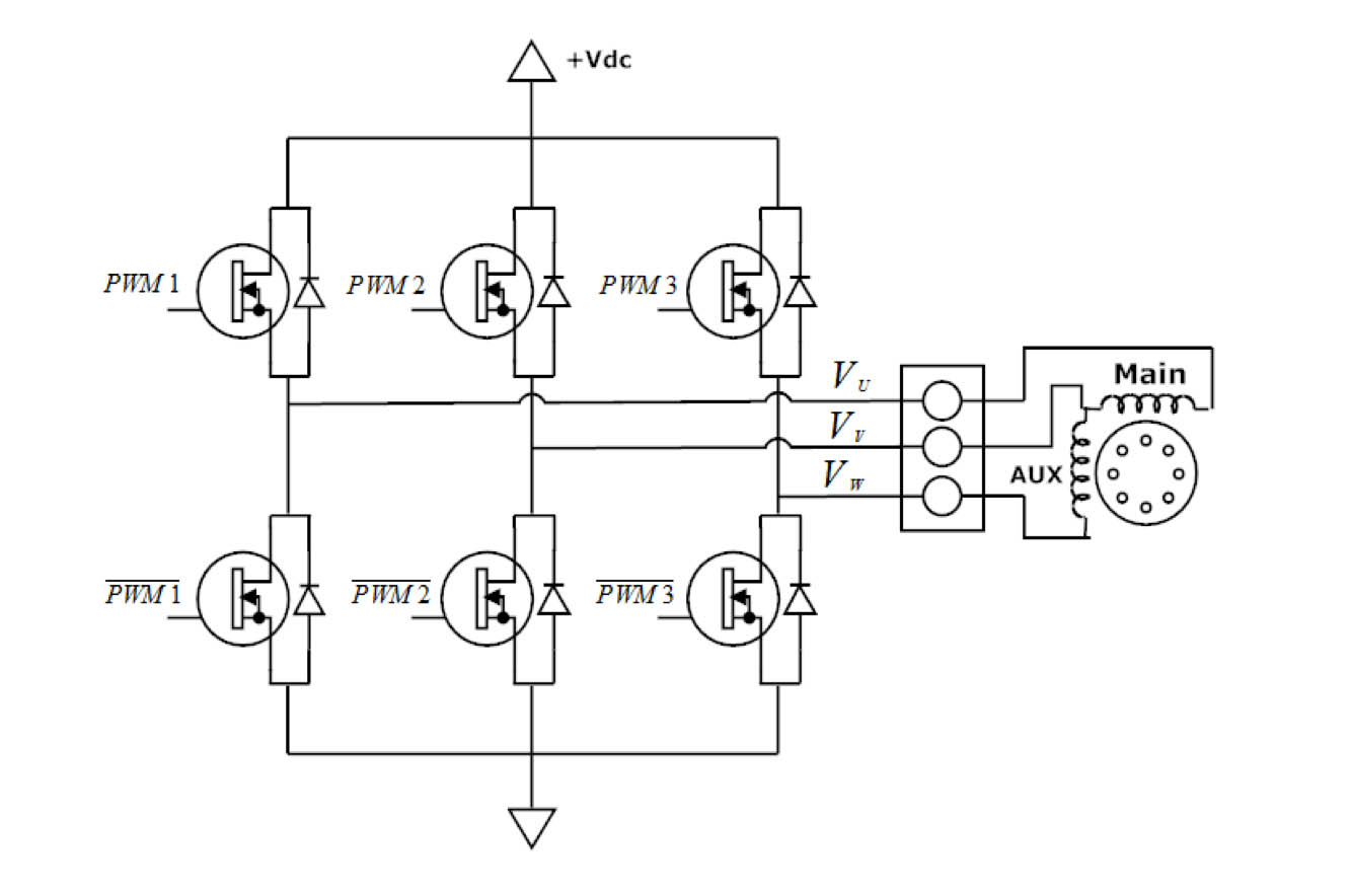
Fig. 2: Single-phase inverter with three half bridges; six PWM signals are used to drive the connected squirrel-cage PSC motor
The motor will still spin without the capacitor if the coils are driven out of phase from one another. This can be achieved by creating three phases in software. These three-phase voltages can then be referenced from one another to create two resultant waveforms across the two motor windings. One of the phases is taken as the reference, or neutral, to create the two waveforms. The three phases can be created in software using PWM techniques.
Comparison
Three tests can be run to compare the PSC run method with the inverter method with no run capacitor. These are: torque to characterise the effects of variable frequency drive on the motor; acceleration and speed to identify which method turns the motor shaft the fastest and how quickly the load will accelerate; and efficiency to compare the real component of the output power to the input power and to measure the power factor and other inefficiencies.
These three tests cover the largest design considerations in motor control. None of the tests require a special setup from the other tests. Each analysis in the three separate tests can use the same subset of data. The test set up is shown in Fig. 3.
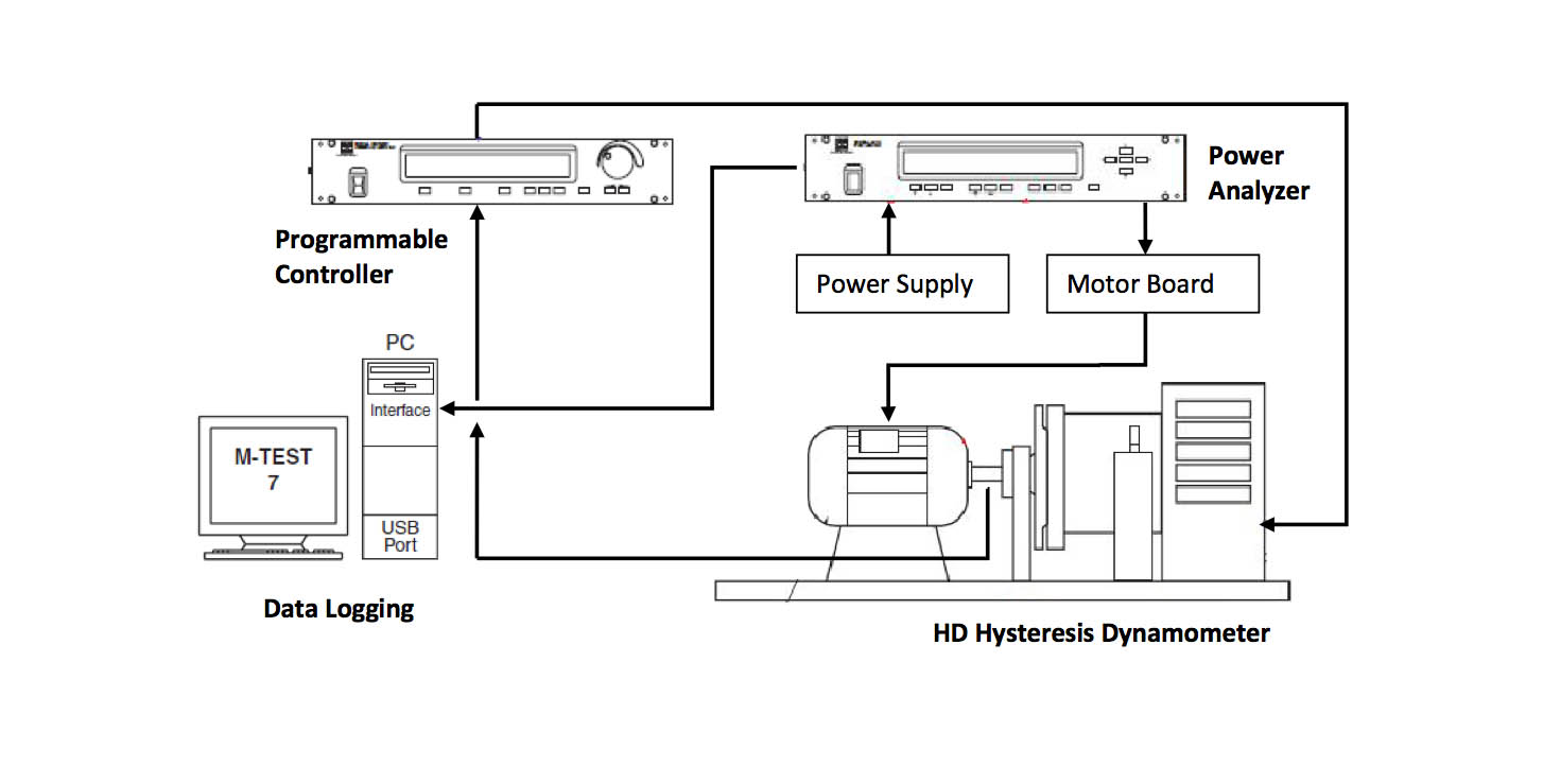
Fig. 3: Test set-up on the dynamometer
This test used a 0.19kW single-phase motor with a balanced wiring configuration. Both windings had identical resistance and inductance. A Hall-effect sensor was used to measure the shaft speed. The input was a single-phase, two-wire 220V at 60Hz. The output was fed into the two terminals on the inverter.
The PC interface ran Magtrol’s M-Test 7 software. The programmable controller applied the test set-up from this software to the dynamometer and read the applied torque. The power analyser performed and logged all the other readings.
Starting with the torque test, it was apparent that the motor had the highest starting torque of around 0.75Nm between 50 and 60Hz in line with the motor design. Frequencies above and below 60Hz had lower torque profiles. However, the low frequency readings did not produce a constant torque curve. Frequencies lower than 60Hz required a fine tuning of the voltage-frequency ratio because of losses in the motor and inaccuracies in the motor drive. Frequencies below 60Hz were kept at maximum voltage.
A low frequency causes a decrease in an inductor’s impedance. The high voltage applied to this lowered impedance raises the current in the stator, which produces higher torque. The fine tuning is needed to make the torque curve linear.
The shapes of the curves between the two methods differ greatly. The capacitor method shows a slightly larger starting torque and will accelerate faster than the inverter board at 60Hz. The inverter board produces a curve similar to that of a class D design motor, while the PSC run topology produces a similar class A torque curve. An unequal voltage magnitude caused by the permanent capacitor creates an unequal magnitude of magnetising flux within the stator. The inverter board attempts to create an equal amount of current in each winding, since this particular motor has identical impedance in each. The shape of the torque curves are not similar because of these discrepancies in the driving topologies.
Looking at the starting torque when the rotor is locked, the inverter would be unable to lift the same-sized load as the PSC method if the inverter were programmed to simply turn the motor at a 60Hz modulation frequency. However, the inverter board can use variable frequency drive to lift an even larger-sized load. The designer must also take into consideration the trade-offs of large starting torque versus efficiency and speed.
The most obvious benefit of controlling the voltage and frequency is that the designer can control the speed at which the motor shaft spins. The faster it spins, the sooner the load can be pushed or pulled to its destination. This can be a critical design win in a garage door or gating system application.
Inverter board
So, the inverter board allows the motor to out-pace a replica motor that is driven by the PSC method. The PSC method can only be driven at one frequency and, hence, it cannot exceed its synchronous speed.
The inverter board can be constructed as an application-specific platform rather than a general-purpose demo board. However, it does provide numerous inputs and outputs (I/O) for the user to interact with and modify. The inverter is engineered to drive a single-phase or three-phase AC induction motor. An overview of the board is shown in Fig. 4 using a PIC16F1509 microcontroller from Microchip.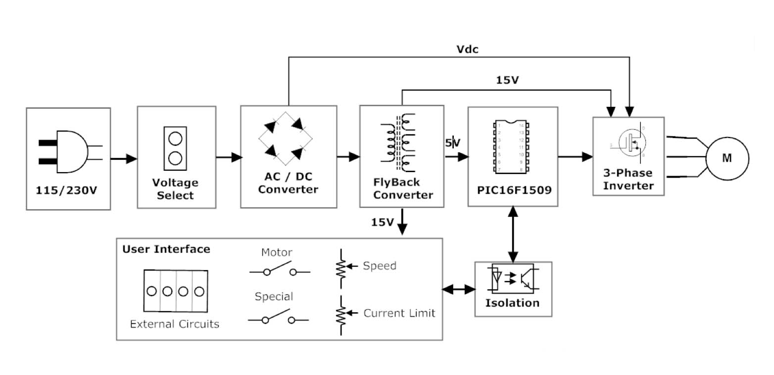
The board was designed with flexibility in mind, so some of its features can be used or not to achieve optimisation. Most of the I/O are used by the default code but there is still plenty of space for the developer to use custom modifications. The I2C lines are also free for any added slave devices.
Some of the I/O are multiplexed onto one pin to increase the number of I/O that can be used. All user interface requirements are isolated via two four-channel optocouplers and a one-channel optocoupler.
The board provides two switch buttons and two potentiometers. There are also headers that provide connections for external I/O, such as garage door trip sensors. The two potentiometers have their transistor in the optocoupler circuitry biased in its amplifying region. The output is therefore approximately linear, since the optocoupler LED does not have a linear I-V curve. Large currents in the 30mA range are consumed for each potentiometer.
The digital push buttons and auxiliary inputs are biased to cause an interrupt-on-change (IoC) when either is used. This alleviates the CPU from constantly checking the voltage level on the pins. Whenever an IoC is detected, an ADC reading must be taken to determine which input caused the interrupt.
Operation
The motor is in its idle state when the PIC16F1509 microcontroller initialises pins and stops the motor. When the start button is pressed, the motor starts using a soft-start method where the frequency and voltage are adjusted in a linear fashion to bring the motor up slowly to its operating speed. The motor then moves to its on state when the soft-start operation is completed.
The motor speed and current trip points are constantly polled in the main loop. If an over-current is detected, the motor is stopped and the status LEDs blink to indicate a fault. The motor is normally stopped by push-button using braking or soft-stop to return it to its idle state.
Conclusion
AC induction motors such as used in garage door applications can be driven using an inverter board rather than a traditional capacitor. This allows speed control and soft-start capabilities to be added to the motor at relatively low cost. The inverter board is based around a PIC16F1509 8bit microcontroller from Microchip.