Abstract – The Gyro klystrons are vacuum electronic devices which can produce high power in the millimetre and submillimeter wave bands. They are part of gyro – device electron cyclotron master family. Gyrotrons and Gyrotron backward wave oscillators are able to provide precise amplitude and phase control. Typical applications are for communications and electron spin resonance spectroscopy. Gyro klystrons are capable of high gain and high-power amplification of electromagnetic waves in a narrow bandwidth. There some types of Gyro klystrons, two cavity device, two-clustered device with two cavities in each cluster, four cavity device, and two cavities in the cluster. The process of designing a Gyro klystron has some steps, choice of the RF operating mode which is correspond to the RF interaction structure, electron beam parameter, and magnetic field. Based on its cavities shape, size and connecting drift tube radii are selected. An electromagnetic analysis of Gyro klystron structure is carried out in the absence of the electron beam, cold analysis. The results obtained from the cold analysis are used to predict the electron beam and RF wave interaction behaviour of the Gyro klystron device in the presence of the electron beam which is not analysis. The Gyro klystron types input parameters are beam current, voltage, transverse to axial beam velocity ration (pitch factor), guiding centre radius and magnetic field values. The operating current and the magnetic field are chosen by the start oscillation current criteria for stable operating of the device. The clustered cavity gives the option for the bandwidth of two high power conventional klystrons to be doubled without changing the overall dimensions of the tubes and minimal degradation in efficiency or gain. The cavities in the cluster are uncoupled. It is achievable to get the separation by short cutoff tubes between cavities. When there are limitations on the length of the device and the beam current the clustered cavity scheme is referred (gain plot as functions of ). The microwave amplitude, phase and frequency are best modulated at low power level (Gyro amplifier) and translated to high power levels with amplifiers. The source of MW or Tera Hertz radiation required by DNP/NMR is Gyrotron. In DNP/NMR experiments it is important to get a good transmission of the generated THz radiation from Gyrotron to the sample.
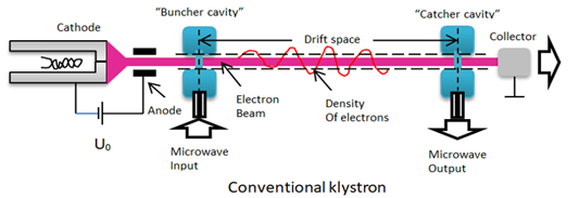
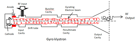
The gyro klystron structure is based on the basic functionality as a high-power microwave amplifier. The gyro klystron structure includes cyclotron resonance, magnetron injection gun (MIG), multiple resonant cavities. We need the strong longitudinal magnetic field for device operation and amplification of the millimetre wave signals. The basic operation is based on modulating the transverse velocity of a helical electron beam. The outcome is high frequency and high-power output radiation wave at frequencies higher than the frequencies of conventional tubes. Typical gyro klystron structure includes the following block devices, (1) magnetron injection gun (MIG), (2) input cavity, (3) drift space, (4) output cavity, (5) collector, and (6) solenoid magnets. The magnetron first generates rotating and hollow annular electron beam, then the RF signal is injected to the cavity. We get result of velocity modulated the helical electron beam. There is a space between cavities (drift space) where electrons from bunches and by that it allows energy gain. In the output cavity the electrons interact with EM field and the energy is transferred to the RF field. The configuration drawing of the Conventional klystron is described (Fig.1).
The configuration drawing of the Gyro klystron is described (Fig.2).
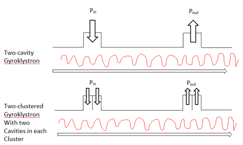
There are two basic gyro klystron structures, (1) two cavities gyro klystron, and (2) two cluster gyro klystrons with two cavities in each cluster. The methodology structure of moving from a two cavities gyro klystron to two cluster gyro klystrons with two cavities in each cluster is presented (Fig. 3).
Fig. 3 Structure of moving from a two cavity Gyro klystron to two clustered Gyro klystron with two cavities in each cluster
The typical gyro klystron multiple cavities devices at Ka – band and W – band main features are described in the next table (Table 1).
| Frequency band regime | Type of Gyro klystron | Output power and peak power | Center frequency | Operation mode and efficiency, Gain |
| Ka – Band
(27GHz – 40GHz) |
Two cavity Gyro klystron | 750 kW | 35 GHz | TE021 mode 24% Efficiency, 20 dB gain |
| Ka – Band
(27GHz – 40GHz) |
Two, Three, and Four cavities Gyro klystron | 200 kW | Millimeter wave radars | N/A |
| W – Band
(75 GHz – 110 GHz) |
Four – cavity Gyro klystron
Amplifier |
100 kW peak power & 10 kW average power | 94 GHz, Bandwidth is 700 MHz | N/A |
| W – Band
(75 GHz – 110 GHz) |
75 kV, 17A Electron beam | Peak power 340 kW | 93.2 GHz, 0.41% (380 MHz) bandwidth | TE021 mode, 27% Efficiency, 23 dB saturated gain |
Table 1. Typical Gyro klystrons multiple cavities devices at Ka – band and W – band main features
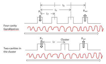
The resonant behaviour of the gyro klystron interaction structure is viewed by the electromagnetic energy decay inside the cavity. At the gyro klystron output end, the net electron energy and power are decreasing which indicate that energy is transferred from electrons to the RF wave. The RF input signal is applied to the gyro klystron input cavity with input driver. We compare between four cavity gyro klystron and clustered cavity gyro klystron. We want to get a high power, large bandwidth gyro – amplifiers for high performance radar applications. Gyro klystrons (GKLs) give a high gain and high efficiency amplification of millimetre waves in a relatively narrow bandwidth. The gyro klystron bandwidth is increased by using clustered cavities. The clustered cavity gives the option to the bandwidth of two high power conventional klystrons to be doubled without changing the overall dimensions of the tubes and minimal degradation in efficient or gain. By using the clustered cavity gyro, the bandwidth of gyro klystrons can be enlarged, while the efficiency of the device is the same as in conventional gyro klystron or higher. The gain in the device of drift section length is increased. A one resonator in the conventional tube can be replaced by a couple or triplet in the clustered cavity device. The scheme includes four cavity GKL and three stage GKL. The first and last stages represent single cavities, and the intermediate stage is a cluster which consist of two cavities (Fig. 4).
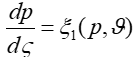
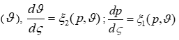
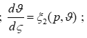
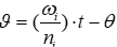
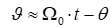
The electron motion in each cavity is described by two equations, one for the normalized magnitude of the orbital momentum (ρ),
velocity, respectively, which are normalized to the speed of light. is the normalized cyclotron resonance mismatch, the functiondescribes the axial structure of the resonator field andis its normalized amplitude,is the field amplitude andis the transverse structure of the high frequency Lorentz force acting on electrons. For cylindrical cavities and annular electron beams the expression foris, where is the azimuthal index of the mode, is its transverse wave number andis the radial coordinates of the electron guiding centres, is the azimuthal coordinates of the electron guiding centres.
Reference
The proposed acquisition would connect PTC’s CAD, PLM and engineering-data platforms with Schneider Electric’s automation,…
The PCIe Gen4 reference design combines high-speed USB data with up to 36 W of…
The OG05D combines a 2.2 µm global-shutter pixel, single-exposure HDR and enhanced near-infrared sensitivity for…
The Swedish semiconductor-equipment company has started a six-month assessment of its advanced patterning process within…
Aivaro AI Feature Detection identifies, classifies and measures defects inside Leica’s Enersight inspection environment without…
Dual-side cooling (DSC) shrinks package footprint by 57% compared with TOLT, packing more power into…