

You might not think about it, but, on average, you utilize hundreds of microcontrollers (MCU) in a day. Everything from your toothbrush to your car has one or more MCUs inside them. And the number of MCUs you rely on is growing with the rapid adoption of the Internet of Things (IoT) movement.
So, what is this MCU inside everything? Like the name implies, a microcontroller is a small chip that controls something. It does this by processing a recipe, known as the program, which someone has written specifically for a product and stored inside the memory of the MCU. Because it is the program inside that decides how the MCU controls a product, one microcontroller can be used in two completely different products. We will discuss the reason for this later.
Historically, users wanted MCUs because they could process data and solve problems faster than a human could. MCUs also help make products more convenient and consistent in behavior. The microcontroller speed or frequency indicates how fast data is processed and problems are solved. Speed is generally not a big problem anymore. The challenge now is that the MCU needs to be able to solve more complex problems while it is being put on a power diet.
Let’s face it. We all get a little worried and start looking for power outlets when our computer or smart phone battery gets close to zero. Imagine if all your battery-powered products required daily charging. To prevent this, we need to put our devices on a budget. They need to become energy efficient.
In this paper, we’ll discuss how to use the Silicon Labs’ 32-bit microcontroller family (EFM32 Gecko) to maximize energy efficiency in your embedded applications.
What is inside embedded applications?
At a high level, all embedded applications are strikingly similar. Everything from industrial products, like water meters and security sensors, to personal items, including smart wearables, are built from a number of components. These components are connected to each other to solve specific tasks. A typical application includes many building blocks. Here is a list of categories and some common components and functions:
Power management – Battery, regulators, energy harvesting, energy storage
Microcontroller – The brain
MCU support – Extra MCUs/co-processors, memories, external RTCs
Sensors/input – PIR, light, HRM, IMU, GPS, rotation count, capacitive touch
Actuators/output – Display, LED, audio, motor control
Wired connectivity – USB, UART, I2C, Ethernet, CAN, PLC
Wireless connectivity – Radio/RF, Bluetooth Smart, ZigBee, Thread, Proprietary, NFC

All of these components consume energy from your power source. So when building an energy-efficient system, logic dictates that you should choose components within your budget that are inherently energy efficient. This is sometimes difficult because many of the items listed above are highly integrated and combine functionalities. For example, in Silicon Labs Bluetooth Smart MCU, the Blue Gecko, both the bluetooth radio device and the MCU are combined, so the user only needs one device.

Almost always on?
Besides integration, you should also understand the components’ various modes of operation. Most of them have an on mode and an off mode, but there may also be intermediate modes. Let’s explore two analog voltage sensors for a moment. Both the Analog-to-Digital Converter (ADC) and Analog Comparator (ACMP), which are built in to the EFM32 products, can be used to monitor analog voltages in a system. Sensors in a system often produce analog voltages as their sensor output.
The ADC is highly accurate and fast, with a 12-bit accuracy and 1 million samples per second. It also has a fast startup time. The ADC is a typical on/off peripheral, even though sample speed and accuracy can be varied.
The ACMP continuously compares the analog voltage against a pre-set threshold instead of taking individual samples. Startup time is not as important here because it is always running, and accuracy can be traded for current consumption. This allows it to monitor analog voltages all the way down to 100 nA of current consumption.
Which one of the ACMP or ADC is better depends solely on the needs of your application.
Energy Sources
There are many types of energy sources for embedded applications:
- Wired Power – 110 V – 240 V AC, 12 V DC, energy “leeching”
- Batteries – Coin cell, Li-Poly, Li-Ion, alkaline, Super-cap
- Energy harvesting – Light, vibration, thermal, RF
- Wireless Power – Light, magnetic, RF
A single application might use multiple power sources, but common across these energy sources, beyond the wired option, is that minimizing current consumption is key. For example, if you’re building a wired home automation system, you may include a backup battery in case there is a power outage. This helps ensure that not all functionality is lost in an emergency.
The following are topics to think about when choosing an energy source for your application:
Mobility – Can the device move? Does it need to be near a socket?
Lifetime – For how long can the device live before it needs maintenance?
Cost – How expensive is this energy source?
Form factor – What size restrictions does my product have?
Designing with batteries
Let’s say you’re a designer and the specification states that the product or application needs to last for at least three years. You’ve decided to use batteries as the energy source. Now you need to make a tradeoff between lifetime, form factor, and cost.
Let’s consider these two coin cell options:
Option A – CR1616, which comes in a 16 mm x 1.6 mm package with 55 mAh capacity.
Option B – Common CR2032, which has 20 mm x 3.2 mm dimensions with 210 mAh of capacity.

With the CR2032, the average current consumption of your application needs to stay below 8 µA in order to get the desired lifetime of three years. If you go with the CR1616, the application must consume less than 2 µA to achieve the same lifetime. By making your application consume less than 2 µA, you go for the smaller battery, and thus get to a smaller form factor for the product.
Surprisingly, the smaller battery in this case actually has a higher cost than the larger one, so the current consumption reduction does not give a cost improvement when switching from the larger battery to the smaller. However, imagine switching from two of the CR2032 batteries to a single CR2032. That gives both a form factor and a cost improvement. Whether a single smaller battery has lower cost than a bigger one can depend on multiple factors, including product demand and availability.
If your application is a wearable or other rechargable accessory, you may want to bypass coin cell altogether and explore the lithium polymer batteries.
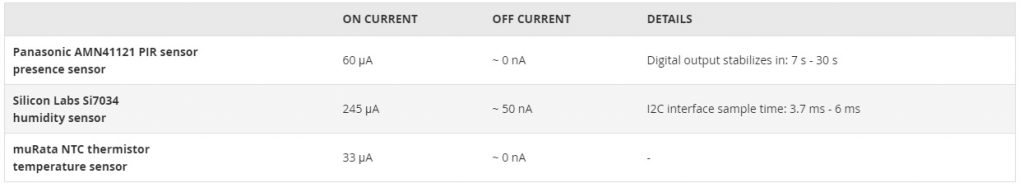
Table 1 – Example component properties. Note that values will vary greatly depending on the chosen components.
Designing with energy harvesting
In general, energy harvesting looks like a very attractive solution. You just use the surroundings to generate the energy you need. But, as with batteries, energy harvesting has tradeoffs to consider. Is the power source reliable? Is your power converter efficient enough? Let’s consider the sun, which is a pretty reliable and sustainable power source. Solar harvesting panels must be in a bright location, and they need to have a given surface area. They might be able to generate 10 mW/cm^2 under direct sunlight, but can drop to 10 µW/cm^2 when indoors. That is 1000 times less energy to play with! To support nighttime operation, a rechargeable battery is needed as well, which increases cost and penalizes form factor.
Designing with wireless power

Figure 1 – Two ways of powering a sensor, in this case a variable resistor, which could be a thermistor. In (A), current is always flowing through the resistors. (B) is much more efficient, only drawing current whenever a measurement is needed. The boxes in the drawing are MCU pins that can be driven high or low by the MCU to control the circuit.
Wireless power delivery, also known as remote power delivery, is similar to energy harvesting in that your application picks up energy from its surroundings. The difference is that in this case, energy is not assumed to be present, in the form of light, vibration, or other natural energy source. A power transmitter generates the energy the application is supposed to pick up.
The challenges with remote power delivery are somewhat similar to those of energy harvesting. For inductive power delivery, the transmitter is generating an alternating magnetic field, and the receiver uses a coil to capture the energy. In this scenario, the maximum distance between the transmitter and the receiver, and also the amount of power that can be delivered, are based on the size of the coil. This puts constraints on form factor and flexibility. Qi and A4WP are two emerging standards for inductive wireless charging, which is currently being used in a number of smart phones and weareables. These require the receiver and transmitter to be in very close proximity, and allow very little mobility. They are thus really only suitable for applications such as wireless charging.
Another method of remote power delivery is based on radio frequencies. By outputting a strong radio signal, and using beamforming techniques, a transmitter can send a signal carrying sufficient energy to a receiving antenna. Challenges with this technology currently include transmission efficiency.
Deciding which energy source to choose for an application depends on the properties of the application itself. The rest of this discussion will dig into applications that operate from constrained energy sources.
Energy Efficiency – The Big Picture
Sensors are the eyes and ears of an application. Table 1 below contains a list of sample sensors and their basic specifications.
When working with a sensor in an application, the straightforward approach is to leave the sensor on all the time, as shown in case A of Figure 1. With this approach, the MCU can read the voltage across the variable resistor at any time, and calculate the current temperature based on the voltage.
This option is the easiest way to control the sensor, but it’s also the method that consumes the most energy. Now, 33 µA might not seem like much, but when a solar cell that small only produces 10 µW of current, we quickly see the problem. A better setup is shown in case B of Figure 1, where the MCU is able to control the power of the sensor directly, turning it on only when needed.
In (A), current is always flowing through the resistors. (B) is much more efficient, only drawing current whenever a measurement is needed.
The boxes in the drawing are MCU pins that can be driven high or low by the MCU to control the circuit.
For an application that only needs to measure temperature once per second, the current consumption of the thermistor is now reduced to 0.165 nA. Assuming that you keep it on for 5 µs in order to sample it once every second, this approach gives you a 200,000x improvement in current consumption.
When controlling the supply of external components through a pin on the MCU, you have to clearly define the default state of these circuits. On EFM32 products, all pins are floating when the device comes out of reset, which, in this scenario, is not an issue. For a device with default-low IO, you want to connect the sensor as shown in case B of Figure 1. But if the IO comes out as default-high, you should connect the other end of the resistor divider to VDD (supply) instead of ground. This will prevent current consumption through the sensor during MCU reset.
An application can consist of a number of components, and you have to make a decision on how to control each component in the most efficient way. Note that designing for energy efficiency actually has a cost. In the thermistor example above, an extra MCU pin is required to control the power to the thermistor. Additional attention to efficiency also has to be given during software development.
Designing for energy efficiency can in some ways be harder than designing a system that does not care about efficiency. But in energy-constrained systems, it is well worth the investment.
What about the MCU?
We discussed that the application components must be duty-cycled in order to maximize efficiency. The same is true for the MCU itself. Because they are more sophisticated components, MCUs almost always have more than just an on/off button. MCUs have multiple energy modes, where each mode allows a set of capabilities with an associated current consumption overhead.
Table 2 shows an overview of the energy modes of the EFM32 MCUs. MCU energy modes will vary somewhat between MCU.
HIGH-FREQUENCY PERIPHERALS
Peripherals requiring a clock in the MHz range. Includes interfaces like UART and USB, high frequency timers, DMA, accelerator engines, etc.
LOW-FREQUENCY PERIPHERALS
Peripherals running off of a slower clock, often 32 kHz, to conserve energy. These allow a high level of functionality even in deep sleep modes. Includes communication interfaces like the UART, sensor interfaces like LESENSE, etc.
ASYNCHRONOUS PERIPHERALS
Using no clocks, these peripherals typically respond to externally generated events. Examples are the pulse counter (PCNT), and the I2C when in slave-mode.
IO STATE AND WAKEUP
The ability to retain the state of the MCU pins and also waking up, giving control back to software, are key even in the lowest energy modes.
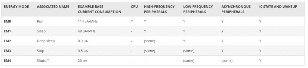
Table 2 – Overview of energy modes on EFM32 Gecko MCUs.
As seen in Table 2, the Run mode (EM0) has all functionality available. As the MCU goes to deeper energy modes, less functionality is available, but drastically lower current consumption can result. There are two key takeaways from this table:
- The CPU is only available in the highest energy mode
In order to reap maximum benefits, the CPU must be turned off whenever it is not needed. The system must aim to sleep as much as possible.
- The system should sleep as deeply as possible whenever it’s sleeping
With deeper sleep, less functionality is available. Thus, the right modes have to be chosen to allow the system to sleep as much and as deeply as possible.
Sleep Mode
A system is said to be sleeping when its main coordinating function is powered down. For a microcontroller, sleep would mean that the CPU has stopped executing code. Since executing code consumes energy, sleeping conserves energy. With deeper levels of sleep, larger parts of the system is sleeping, giving higher energy savings, but with deeper sleep also comes the downside of less functionality available and longer wakeup times.
The EFM32 MCUs are designed to maximize the amount of time that can be spent in sleep modes, also known as energy modes. This is achieved by providing a broad amount of functionality in sleep modes, combined with fast wakeup times.
By requiring the CPU to be off as much as possible in order to save energy, the CPU tasks must be offloaded to the hardware in the MCU. Instead of being in a paradigm where software running on the CPU does everything, software development should focus on setting up hardware to do the heavy lifting and only intervene when hardware needs assistance. In other words, hardware should be the main driver of the application.
This takes the system to an event-driven architecture, allowing massive energy savings. Table 3 shows the sample code of an application that measures temperature using a thermistor, enabling a fan when temperature crosses a determined threshold. This example code assumes that the MCU has hardware that allows it to autonomously monitor the sensor and give an interrupt whenever the sensor crosses a threshold. In the “traditional” approach, this autonomous hardware is used, while in the “event-driven” approach, it is fully leveraged.

Table 3 – Traditional vs. event-driven implementation.
As you can see in the example, the event-driven code is more complex than the traditional code, but it has some significant advantages:
Massive energy savings
A system using the traditional approach running at 10 MHz would consume more than 1.1 mA, while a system using the event-driven approach would consume as little as ~0.9 – 1.3 µA, depending on the sensor and sample rate. This is almost a three-orders-of-magnitude difference. More importantly, it’s the difference between a day and multiple years of battery life.
Multi-tasking
With the traditional approach, the CPU does everything, and can only manage a limited number of functions. With the event-driven approach, the CPU is freed up because hardware does the bulk of the work. With this method, an MCU can drive sophisticated applications.
On an MCU with minimal flash and RAM resources, this is how you should write code. With this kind of multi-tasking you can get the absolute most out of the hardware in the MCU, both in terms of performance and energy savings. We call this “coding down to the metal.”
Spending some of the MCU resources on an embedded operating system provides a level of abstraction that makes building sophisticated, event-driven applications easier, but potentially less efficient. For applications running on MCUs with 512 KB flash or more, the memory overhead can be negligible, making this an easy choice. On MCUs with 32 KB flash or less, there are still operating systems that can do the job, but the percentage of the MCU resources used by the OS increases drastically. A minimal configuration of FreeRTOS requires between 5 KB and 10 KB flash and a minimal amount of RAM.
For complex applications, an operating system might actually make the system more efficient than coding to the metal. This approach gives software developers a framework for how to write code to use energy modes in the most efficient way.
A couple of operating systems or ecosystems to check out are listed below. They all provide tick-less sleep modes, meaning that unlike normal PC operating systems that always waste energy by waking up every 1 ms or 10 ms, these operating systems only wake up when they are needed:
ARM mbed OS
FreeRTOS
RTX
Doing it in your sleep
In the previous section, we talked about the CPU letting hardware do the bulk of the work. While the CPU is sleeping and no software is running, the MCU should autonomously carry out the CPU’s orders. There are two things to focus on here:
Sleep as deeply as possible
Wake up as seldom as possible
Looking back at the thermistor example, there are multiple ways of achieving this with varying amounts of sleep.
- The traditional way
CPU uses ADC to continuously sample the thermistor.
This approach forces the CPU to be awake at all times, causing the highest current consumption. A traditional implementation of this, run on the EFM32 Wonder Gecko, results in the following current consumptions:
- Wonder Gecko, sampling ADC @ 1 Hz: 4.18 mA
- Wonder Gecko, sampling ADC @ 128 Hz: 4.18 mA
Figure 2 shows the system current consumption using the Advanced Energy Monitor (AEM) capability offered by Simplicity Studio, a combination of free tools provided by Silicon Labs. The current consumption is measured in real-time using hardware available on all EFM32 development kits. In this scenario, current consumption is dominated by the CPU, and very little variation can be seen from the ADC activity.

Figure 2 – Wonder Gecko traditional implementation sampling ADC @ 128 Hz.
- Improved
RTC wakes up the CPU periodically. On wakeup, the CPU uses the ADC to sample the thermistor.
With the improved method, the CPU configures the RTC to provide a periodic wakeup. Since the RTC works all the way down to EM2 Deep Sleep, the MCU consumes only 0.9-1.4 µA while waiting for wakeup. On period wakeup, the CPU uses the ADC to take a sample, then potentially performs an action based on the result before going back to sleep. With this approach, the system can see a significant improvement in energy consumption.
RESPONSE TIME
Response time is the length of time taken by a system to react to a given stimulus or event. Faster response times often come at the expense of power consumption, because the event has to be checked for more frequently, and because once the event has been detected, the system needs to be able to respond in time, which could involve waking up from sleep, and the deeper sleep modes require longer wakeup times.
This scenario also brings up the notion of response time. The longer we can wait between samples, the more energy we can save. In a house where temperature changes slowly, the system can wake up to take a sample every 10 seconds. However, this also causes a 10-second reaction time to any temperature change event. In most systems, reaction time is a critical component and will vary with sensor type. Required sample-rate depends on what is being measured. For a heart-rate measurement system, one might want to measure the system 25 times a second. For a rotation-based water meter, up to a thousand times a second.
Power gating also becomes critical in this scenario. Since we are now approaching system current consumptions around 1 µA, the 33 µA, current consumption of the thermistor becomes dominant unless the CPU makes sure the thermistor is powered only when it is being sampled.
Figure 3 shows the current consumption over time for the 1 Hz scenario. The Wonder Gecko consumes 0.95 µA in deep sleep mode, and the periodic wakeups to EM0 can clearly be seen. Note that the current consumption includes excitation of the external thermistor.

Figure 3 – Wonder Gecko, EM2 interrupt driven, sampling ADC @ 1 Hz.
Using this approach, an application can get to the following current consumptions, which is considerably better than the first approach.
- Wonder Gecko, sampling ADC @ 1 Hz: 1.30 µA
- Wonder Gecko, sampling ADC @ 16 Hz: 2.43 µA
- Wonder Gecko, sampling ADC @ 128 Hz: 10.46 µA
- Wonder Gecko, sampling ADC @ 1024 Hz: 72.48 µA
- Optimal
MCU autonomously monitors the thermistor, only waking the CPU when the threshold is crossed.
If an MCU supports autonomous external sensor monitoring while also duty-cycling them, this is by far the most efficient option. Low Energy Sense (LESENSE), available on devices in the EFM32 portfolio, is able to autonomously monitor up to 16 external resistive, capacitive, or inductive sensors, while also properly turning off the sensor when not in use.
LESENSE
LESENSE is a peripheral available on some EFM32 devices, which allows autonomous monitoring of external sensors for things like temperature, capacitive touch, presence of metal, and many other things. LESENSE can monitor up to 16 sensors, and can also autonomously combine sensor results and make decisions based on these without waking the EFM32 up from sleep. The CPU is only woken up whenever LESENSE deems it necessary. The ability to stay in deep sleep modes for the majority of an application’s lifetime has a significant, positive impact on energy efficiency because sleep modes require longer wakeup times.
With this approach, the CPU does not wake up around every sample, as in the second option. It wakes up only when a sample is outside of a set threshold. This concept is demonstrated in Figure 4, where the system is able to stay in EM2 continuously.

Figure 4 – Wonder Gecko, Wonder Gecko, LESENSE, sampling @ 1 Hz.
For a very slowly sampled system, using the ADC as in the second option is better because LESENSE uses some current to operate. But for higher frequency systems, LESENSE definitely has a benefit. It reduces the current consumption by more than 10X in the system sampled at 1024 Hz:
- Wonder Gecko, LESENSE @ 1 Hz: 1.49 µA
- Wonder Gecko, LESENSE @ 16 Hz: 1.57 µA
- Wonder Gecko, LESENSE @ 128 Hz: 2.06 µA
- Wonder Gecko, LESENSE @ 1024 Hz: 5.92 µA
LESENSE can also simplify software development by treating measurements as its own autonomous system, freeing up the ADC for other tasks.
Do even more while sleeping
The thermistor example shows one method of operating an external sensor in a very energy efficient way, assuming that the MCU has the hardware to support it.
There are also other ways of solving the thermistor problem. On the EFM32 Gemstone products, as well as the Blue Gecko, based on EFM32 Gecko technology, the ADC can now operate while the system is in deep sleep mode (EM2). The “improved” approach above, where the RTC/RTCC woke up the CPU to take an ADC sample, can now be changed to making the RTCC automatically trigger the ADC through the peripheral reflex system (PRS). An ADC with these products also has the ability to evaluate the ADC result and only give the CPU an interrupt if the sample is outside or inside given thresholds.
It is important to also duty-cycle the thermistor properly. Where LESENSE does this for you automatically, the ADC does not, and it has to be controlled either via PRS or from the CPU. It makes sense to turn the thermistor on in sufficient time before sampling, and off immediately after. Let us see what happens if we try to use an RTCC event through PRS to enable and disable the thermistor. This scenario is shown in Figure 5.

Figure 5 – ADC sample triggered by RTCC event through PRS
As the figure shows, an RTCC event is longer than the ADC takes to warm up and sample the thermistor. Based on a 32 kHz clock, the RTCC event keeps the thermistor on for 22 µs longer than necessary. You can cut this time down by using some PRS tricks. For example, the ADC produces a short PRS output whenever it is done. Using the RTC event, PRS signal, and the ADC to complete the PRS pulse, it’s possible to create a signal that goes high on the RTC trigger and low when the ADC is complete. This signal can automatically enable the thermistor in the system.
The conceptual circuit for this example is shown in Figure 6. Initially, the latch output Q is low because the RTCC event output and the ADC conversion done output are low. Whenever the RTCC event now goes high, the external sensor is enabled and the ADC starts taking a sample. Once the ADC is done, the conversion done signal goes high, setting the latch output Q high, which forces the external sensor off. When the RTCC event signal goes low again, the latch is reset, making the system ready for the next event.

Figure 6 – Conceptual circuit, which starts external sensor excitation on RTCC trigger, and ends excitation when ADC sample has been taken.
The circuit shown in Figure 6 can easily be implemented on an EFM32 Gemstone MCU using the Peripheral Reflex System (PRS), which contains logic elements that can be connected together in various ways. Figure 7 shows what this implementation would look like using six of the available PRS channels. Table 4 shows how the 6 PRS channels are configured to enable this functionality.

Figure 7 – PRS implementation of circuit performing optimal excitation of external sensor.
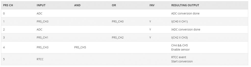
Table 4 – PRS configuration to implement circuit performing optimal excitation of external sensor.
Start conversion
Using the ADC autonomously running in EM2, with PRS for optimal excitation of the thermistor, as we have shown here, shows a fourth way of implementing monitoring of an external sensor. To monitor it autonomously, the ADC was set to test whether the thermistor value was within a certain window, and only notify the CPU if the value happened to be outside.
The results are on par with the results using LESENSE in the previous section, but compared to LESENSE, which uses a comparator for detection, this example employs a full 12-bit ADC, and thus higher monitoring accuracy. Current consumption results are shown below, and Figure 8 shows the 128 Hz scenario in detail.
- Pearl Gecko, sampling ADC in EM2 @ 1 Hz: 2.22 µA
- Pearl Gecko, sampling ADC in EM2 @ 16 Hz: 2.30 µA
- Pearl Gecko, sampling ADC in EM2 @ 128 Hz: 2.75 µA
- Pearl Gecko, sampling ADC in EM2 @ 1024 Hz: 6.51 µA

Figure 8 – Pearl Gecko, EM2 autonomous, sampling ADC @ 128 Hz.
What we have built here is an autonomous system customized to do a specific task in hardware, allowing the CPU to sleep as much as possible. The above is simply an example, and many other configurations are possible. Low power applications like this are enabled on the EFM32 platform because of a wide range of low energy mode functionality in the MCU itself:
Analog functions (ADC, DAC, ACMP, and IDAC) operate down to EM3
Most communication interfaces have modes allowing them to operate down to EM2/EM3
Low power timers have broad amounts of functionality: LETIMER, RTC, and RTCC
Specialty hardware (e.g. PCNT and LESENSE) allows complex operations that would normally require the CPU
As an example, the pulse counter (PCNT) can monitor higher frequency processes all the way down to EM3:
Monitor absolute rotation or translation through an integrated quadrature decoder:
Wake up or notify the PRS on a direction change, absolute rotation, or absolute position
Monitor signal frequencies:
Wake up or notify the PRS on a frequency change
Monitor event counts
Number of ADC samples taken, PWM pulses generated, etc., through PRS
Number of excitations from external sensor or other device through IO
Optimizing the system
The discussion so far has considered a system dealing with a single function and a single source of wakeups. Imagine a system with ten different components that need to be managed. Some can be controlled fully autonomously, like the thermistor above. For others, the CPU might have to wake up periodically in order to take control.
If care is not taken with such a system, it can end up in a situation like the one shown in case A of Figure 9, with many more wakeups than necessary, resulting in a less efficient system. The figure shows two deterministic processes, which execute periodically, and one sensor event, firing nondeterministically. In case A, the processes arbitrarily wake up to perform their tasks, which results in a total of 11 wakeups, wasting a significant amount of energy due to the time it takes to transition between sleep modes.
To improve on case A, you can do sleep planning. For all deterministic processes, i.e. processes we know of beforehand that are going to require a wakeup, care should be taken to align the wakeups as much as the system allows, minimizing the number of wakeups.
In case B, the wakeups by Process 2 have been aligned with the wakeups from Process 1, resulting in a total of 6 wakeups during the same period, a significant reduction from case A.

Figure 9 – Sleep Planning. The black segments show time wasted due to wake-up time from deep sleep modes.
Sleep planning
As we have discussed, minimizing awake time is important. In many cases, software running on the CPU is waiting for something to happen. If the CPU is set to wait for a fixed time, the best approach is to use a hardware timer. Hardware timers come in a range of types with varying functionality, current consumption, and accuracy.
On an EFM32 system, if the CPU needs to sleep for a short number of clock cycles while maintaining full MCU operation, the software should use the TIMER peripheral and place the system in EM1 while waiting. This method will significantly reduce current consumption, and wakeup is instantaneous.
If only EM2-EM4 level functionality is necessary while waiting and the wait-time is more than 31 µs, the period of a 32768 Hz oscillator, the low-frequency timers LETIMER, RTC, or RTCC can be used and the system can go to EM2 for maximum efficiency. If high accuracy is required, a TIMER can be synchronized to the low-frequency timer upon wakeup through PRS to time out the last clock cycles with the accurate high-frequency TIMER.
If wait time is relatively long, i.e. multiple milliseconds, and does not have to be accurate, and the system only needs EM4 functionality while sleeping, sleep can be done using the CRYOTIMER, running on the 1 kHz ULFRCO oscillator for extremely low sleep current in the 100 nA range. Note that wakeup from EM4 costs more energy than wakeup from EM2, because the wakeup is through a reset, so even though EM4 could be used for sleeping for 5 ms, it might not be the most energy efficient. With sleep times of minutes or more, EM4 starts becoming extremely efficient.
Note that on EFM32 devices, a write to the low-frequency timers (LETIMER, RTC, or RTCC) is instantaneous, compared to other MCUs, where a write takes multiple low-frequency cycles. This means that on EFM32, if the RTC value is currently 99, the MCU can decide to go to sleep and wake up on value 100. For most other systems, the earliest RTC value possible to wake up on would be 102, making it difficult to sleep if the wait period is less than 100 µs.
CPU efficiency
No matter how much you try to optimize for sleep, the CPU needs to execute code now and then. This can include everything from regular application logic to network stacks and signal processing algorithms. The CPU is an important part of the MCU.
Here are the top five items to ensure the CPU runs code efficiently:
- Let the compiler optimize your code.
This tip might seem obvious, but make sure the code is compiled with full optimizations enabled. If the compiler is able to do link-time optimization, use this as well. Code compiled for debugging is inefficient on many compilers, one reason being that values are fetched from memory, calculated and then written back on every operation. Without optimization, it is also not fully utilizing the capabilities of the CPU, which also slows down execution.
- Target the right architecture.
Choose the right CPU for your application and ensure that the compiler creates code optimized for that correct device. For example, Cortex M4 is excellent for bigger applications that contain number crunching. Cortex M3 does not have all the DSP capabilities and no floating point, compared to the Cortex M4, but is still relatively high performance. Cortex M0+ is the most efficient of the bunch as long as the amount of signal processing is at a minimum. It is excellent for stacks and control logic.
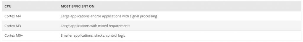
Table 5 – Simplified overview of ARM Cortex M CPUs
- Operate at the right frequency.
Even though lower frequencies give lower current consumptions, it is generally better to finish the job quickly to be able to go to sleep; in other words, a higher frequency might give better energy efficiency. If the different parts of the system require different needs (i.e. USART needs 4 MHz, but the CPU needs 8 MHz), use pre-scalers for clock domains to make the frequency selection optimal.
- Use available hardware accelerators.
Some operations perform more efficiently in hardware than on a CPU. One example is cryptography. The CRYPTO peripheral available on the EFM32 Gemstone devices can complete operations more than 10 times faster and much more efficiently than running them on the CPU. Another example is the alpha blending hardware on some of the EFM32 products. This hardware makes graphics compositing for external displays more efficient.
- And, of course, sleep whenever possible.
Hardware efficiency
So far, we’ve focused on how the MCU is inherently efficient and can control the application in an efficient manner. The picture is almost complete. The remaining details must center on how the hardware is built, as well as how energy is stored and supplied to the system.
While this topic is too broad to delve deeply into here, one important point is operating voltage. In general, the lower voltage supplied to a component, the more efficient the component is, down to the functional limit of the device. A lot of traditional components have operating voltages around 3 V, but we’re seeing a shift toward components running at a nominal 1.8 V.
This improvement is great for energy efficiency; however, a lot of energy sources, including coin cell batteries and lithium polymer batteries, output much higher voltages than this. In order to regulate the voltage down to the target voltage of the system in the most efficient way possible, you should use an efficient switched-mode buck converter (DCDC).
Some of the EFM32 Gemstone devices include a built-in DC-DC converter, able to supply both the MCU and external components with a total of up to 200 mA. This allows you to build a highly energy-efficient system without adding external converters.
For example, a 3 V lithium coin cell battery would have a mean voltage output of around 2.8 V. Using an LDO to regulate down to 1.8 V results in efficiency of around 64 percent. However a switching DC buck converter could regulate the same 1.8 V supply with efficiency of over 80 percent, which would extend the battery life by more than 25 percent, perhaps turning a four-year battery life into five years. Note that there is a small additional cost associated with using even an integrated switching converter, as it requires an external inductor and some capacitors to be added to the PCB. In most applications where low power is important, this is a small price to pay for a significant increase in energy efficiency.
Conclusion
At the heart of most embedded products lives a microcontroller with power sources that may be limited to small coin sized batteries. When focusing on using available power more efficiently, designers will be able to create energy-friendly products and applications that are smaller, have longer battery life and cost less. These applications can then also use alternative and limited energy sources, such as energy harvesting.
In order to achieve this, designers must know how to leverage all the low power capabilities of the MCU that is controlling the application. A product should include hardware that monitors, controls and operates autonomously. This allows the system to be in deep sleep modes for the majority of its lifetime. Attention must be paid to the overall power architecture of the system, while leveraging the MCU to manage as much of it as possible. Whenever software needs to intervene, it should be swift and efficient.
MCUs and RF SoCs from Silicon Labs provide a unique combination of energy efficiency and flexibility. They are built for autonomous operation in deep sleep modes and provide the needed energy efficient for sleepy systems. Highly efficient active modes allow you to use the CPU as well, while staying inside your application’s power budget. Ultimately, this allows smaller batteries or energy harvesting components, giving you the right combination of form factor, cost, and device availability.
Øivind Loe is a senior marketing manager responsible for Silicon Labs’ 32-bit EFM32 Gecko MCU portfolio. He joined Silicon Labs in 2013 following the company’s acquisition of Energy Micro, where he started working in 2008 as a digital design engineer and subsequently played a key role in the development of the EFM32 MCU architecture and product portfolio. Mr. Loe has also served as a design manager at both Energy Micro and Silicon Labs, and now works as a marketing manager at Silicon Labs, focusing on EFM32 technology. He holds a master’s degree in Engineering Cybernetics from the Norwegian University of Science and Technology.


