
Attenuators are 2-port passive devices that can incrementally dissipate microwave energy. They have a myriad of uses and are often applied in test scenarios as padding to prevent damaging sensitive and expensive test equipment. Variable attenuators can be used to control the gain of a system via the output of the microwave source as opposed to varying the input in order to maintain a favorable signal-to-noise ratio. Attenuators are designed to have minimal reflections and a low Voltage Standing Wave Ratio (VSWR) to avoid potentially catastrophic reflections back to the source.
Theory: The ‘cut off’ principle
Waveguide attenuation is often based on the cut off principle where a section of the waveguide is operating frequency far below the cutoff frequency — a frequency that directly correlated with the dimensions of the waveguide, below which the waveguide is unable to carry signals. For a rectangular waveguide, the length of the broadwall is generally equal ½ wavelength of the lower cutoff frequency. Microwave energy will therefore dissipate very rapidly in sections where the H-plane is stunted as shown in Figure 1. This rate of decay is exponential along the transmission path of the signal. As the cutoff frequency increases, so does the rate of attenuation of the modes below cut off frequency. And since waveguides can operate with many modes existing simultaneously, the dominant mode is used; the mode with the lowest decay rate and lowest cutoff frequency [1].
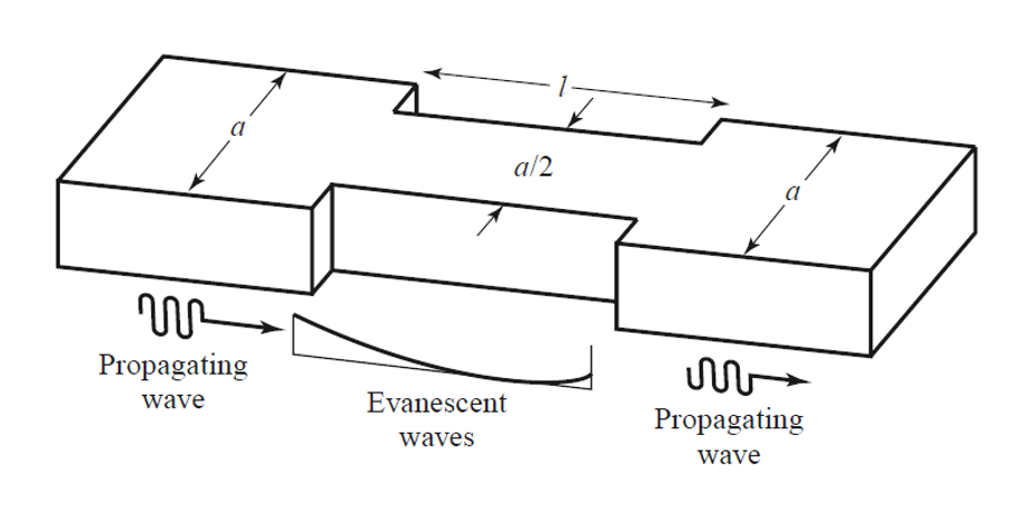
Figure 1: A change in length of the broadwall attenuates the signal rapidly over the length of the waveguide. Naturally, there is also a high VSWR due to the reflections from the discontinuities.
Source: Chegg
The attenuation rate for a rectangular waveguide with the dominant TE10 mode in frequencies under the cutoff can be defined by Equation 1 [2]. The attenuation for a circular waveguide with TE11 mode in frequencies under the cutoff is defined by Equation 2 [1].
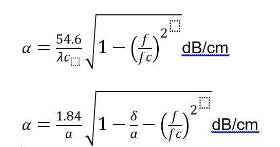
Where is the attenuation, is the skin depth of the guide, a is the radius of the circular waveguide, is the cutoff frequency in GHz, and is the cutoff wavelength in centimeters.
Fixed Waveguide Attenuator
Fixed waveguide attenuators typically include a resistive film such as glass placed inside of the waveguide. As shown in Figure 2, the resistive card is placed at the center, parallel to the longitudinal axis and to the maximum electric field with each end tapered sharply to point directly at the incoming wave in order to minimize reflections due to discontinuities. The length of the material is typically two wavelengths (2ƛ) while the length of the tapered portion is about a half a wavelength (ƛ/2). In essence the bulk resistive material accounts for a uniform insertion loss across select frequencies while the taper is fine tuned for a lower VSWR.
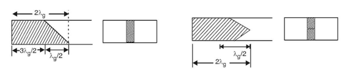
Figure 2: The resistive element causes attenuations while the taper minimizes reflections. The taper shape can vary with a single taper or a double taper.
Continuously Variable
A continuously variable attenuation is accomplished in a waveguide by means of vertically adjusting the lossy dielectric fins to incrementally reduce the energy level of the signal at the output. This can be done with either a micrometer screw (Figure 3a) or with a flap-type adjustment where the attenuating material is mounted to a movable arm (Figure 3b). The greater the penetration of the lossy vane, the greater the attenuation. The dielectric slab can be specifically shaped (and is often disc-shaped) so that the attenuation can vary linearly with insertion.
The flap-type waveguide attenuator has gone through several iterations to improve the linearity of the insertion loss over mechanical positions. Older constructions involved suspending the element manually to preset fixed positions that could vary over time with wear and tear thereby risking oscillations [6]. Some constructions involve a disc-shaped insulator material suspended into the waveguide via a mounted holding structure. The continuous rotation of one side of the disc yields a sinusoidal attenuation while the other side of the disc has been shaped to compensate for the phase shift in precision applications [5]. More precision flap-type attenuators are adjusted via a plane orthogonal to the moving arm so that the element is inserted into the waveguide as a function of angular position [4].
Figure 3: Manual variable attenuators employ some type of mechanical adjustment such as a screw, micrometer, or knob. Motorized attenuators require continuous spinning of the resistive plate where variable control is often accomplished with voltage-tuned motors.
These attenuators are not designed specifically for high powers due to the poor thermal management of the resistive component. For instance, high powered coaxial attenuators contain resistive elements on a ceramic insulating substrate that are in direct contact with a heat sink where heat can be carried away rapidly by the anodized aluminum fins [3]. This cannot be accomplished in a waveguide attenuator where the resistive card is suspended in the waveguide cavity as there is generally no effective way to place a heat sink for suitable heat dissipation. Since the dielectric naturally has far less thermal conductivity than metal, these attenuators cannot be used in high powered applications.
Rotary Vane
Rotary vane attenuators typically consist of three sections of circular waveguide that contain a particularly shaped resistive card. As shown in Figure 4, the middle section is rotated axially while the ends — typically a rectangular-to-circular waveguide — remain static. When all three resistive cards are flat, or normal to the electric field, no attenuation takes place. Full absorption occurs when the central resistive card is rotated 90o, or parallel to the electric fields [9]. Variable attenuation values occur at particular angles with reference to the electric field, allowing for a highly precise insertion loss. The benefit of this device is the precision and bi-directionality while some design considerations may be the phase shift and length that vary as a function of frequency. Furthermore, cooling for these types of attenuators may be difficult to achieve as the dielectric substrate is once against hard to reach the resistive vane within the waveguide.
Figure 4: Rotary vane attenuators have three sections with the center rotating with respect the electric-field. These types of waveguide attenuators are generally the most precise.
High Power Waveguide Attenuators
High Power Rotary Vane
Another version of the rotary vane attenuator involves slits that run the length of a circular waveguide. Microwave energy is attenuated as the position of the slit is rotated by means of resistance to currents in the walls of the waveguide. The energy is then dissipated via a parallel plate transmission line near the slot. The lossy parallel plate transmission lines can then be mounted to a thermally conductive surface for simpler thermal management. Moreover, convective cooling can be provided with liquid or air distribution in the enclosure [10].
High Power Variable Attenuator
High power variable attenuators often have three ports where one allows for the microwave energy to be terminated some sort of high power absorbing load. One construction involves a 3-port circulator within the transmission line that controls the signal transmission such that the input energy is sent into the second port where the tuning occurs. In this port, the waveguide can be tuned so that the reflected portion that is sent back into the circulator and to the output (third port) to yield a particular attenuation value. The rest of the signal at the second port is absorbed by the load which can much more easily be convectively cooled with water or circulating air [11].
Summary
There are essentially three types of waveguide attenuators: fixed, continuously variable, and rotary vane. While all these attenuators exploit the cutoff frequency principle, each subset has many electromechanical design variations that can be optimized for more precision, lifetime, VSWR, or power handling. The best construction for a particular application depends on some of these variables. Waveguide attenuators offer a simpler design with far less VSWR than their coaxial attenuator counterparts since an engineer will have to take into account the losses due to the waveguide-to-coaxial adapters.
References:
- Adair, Robert T. “A precision 30 MHz waveguide-Below-Cutoff attenuator with an absolute electronic readout :” 1976, doi:10.6028/nbs.ir.76-833.
- https://www.electronics-cooling.com/2017/11/thermal-management-considerations-high-power-coaxial-attenuators-terminations/#
- https://www.electronics-cooling.com/2017/11/thermal-management-considerations-high-power-coaxial-attenuators-terminations/#
- https://www.google.com/patents/WO1999001906A1?cl=en
- https://www.google.com/patents/US3209288
- https://www.google.com/patents/US2619538
- Das, Annapurna, and Sisir K. Das. Microwave engineering. Tata McGraw-Hill, 2009.
- https://www.google.com/patents/US2603710
- Fundamentals of Microwave and Radar Engineering By K K Sharma.
- https://www.google.com/patents/US3562679
htt


