

A look at how a virtual controller can be set up to save cost and CPU time when rendering graphics
One of the popular ways of creating graphical embedded applications is to add an internal or external graphics controller. The problem is that this adds cost and can make designs unnecessarily complex, and in most cases for a simple graphical user interface such controllers are not needed.
An alternative is to use microcontroller peripherals to create a virtual graphics controller for graphics rendering without taking up large amounts of CPU time, in fact it can be less than five per cent.
In general, a controllerless graphics system needs to send a frame of pixel information to a display glass at a certain rate. This refresh rate is usually around 60Hz. To do this, the system must constantly send frame data to the LCD panel. At first, it seems like this task would take up most of the CPU time in an MCU. However, this is not the case for microcontrollers, such as Microchip’s PIC32 MCUs, that contain a direct memory access (DMA) peripheral for data transfer. With a DMA transferring the pixel data, less than five per cent of CPU time can be used to achieve a virtual graphics controller.
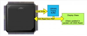
Fig. 1: External memory method
The DMA peripheral can transfer data from one location to another without CPU intervention. In a controllerless graphics method, the DMA can be set up to transfer one line of frame data at a time through the parallel master port (PMP). Each line consists of many pixels. The DMA would send a portion of the frame buffer during one transfer. A PMP or timer interrupt request would then trigger the next DMA transfer until a line is transferred. In devices with non-persistent interrupts, a timer can be used as the DMA trigger source.
For devices with an external bus interface (EBI), this module can be used as a pixel clock source. Such a clock source can achieve faster pixel clock speeds than the PMP peripheral, yet the EBI shares the same pins as the PMP.
During data transfers, the PMP or EBI strobes a read or write signal after each pixel transfer. The read-write strobes act as the pixel clock for the display glass. After each line of pixel data is transferred, the CPU is interrupted by the DMA and certain timing signals – such as HSYNC, VSYNC and data enable line (DEN) – needed for LCD panels are updated. This is repeated continuously until an entire frame has been drawn. The frame is stored in volatile memory so the image can be dynamic.
In this setup, SRAM is used and the configuration is the foundation for a controllerless graphics system. The system can be set up to use internal or external SRAM, as shown in Figs. 1 and 2.
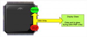
Fig. 2: Internal memory method
TFT LCD panels
Though the controllerless graphics method was designed to work with TFT LCD panels, it can also work with CSTN or MSTN glass with minor modifications. The data lines consist of the pixel colour information. Most LCD panels can have eight to 24 colour data lines depending on the colour depth of the LCD panel. These data lines supply the LCD panel with the raw colour data of each pixel.
The HSYNC, VSYNC, DEN and PCLK clock signals synchronise the pixel data with the graphics frame and the LCD panel. The sync lines tell the LCD panel when the data are at the start or end of a line (HSYNC) or a frame (VSYNC). The DEN lets the LCD panel know when valid pixel data are being sent to the LCD panel and is required for some TFT LCD panels because of the time needed to set up the LCD panel for proper pixel locations.
Data are sent one line at a time until the entire frame is drawn. The PCLK signal is the clock source for the whole system. One clock pulse from the PCLK updates the LCD panel. All other clock lines must be synchronised to the pixel clock to achieve proper image output. LCD panels not containing HSYNC and VSYNC signals can still be used with the controllerless graphics setup.
Microchip’s Low-Cost Controllerless Graphics PICtail Plus daughter board (LCC graphics board) was designed to demonstrate this technique and works with many existing PIC32 starter kits. The LCC software driver can help with synchronisation needing certain timing parameters, such as pulse width, front porch and back porch for horizontal and vertical pulses. After these values are compiled into the LCC graphics driver, the LCD panel displays the frame.
Fig. 3 shows what happens inside the PIC32 microcontroller when a graphics frame is being sent to the display. The DMA and PMP block indicates what the DMA and PMP peripherals that share the data bus with the CPU are performing. The CPU block indicates the tasks required for graphics rendering. The DMA interrupt service routine (ISR) is the only code that must be written besides setting up the DMA and PMP peripherals to send a graphics frame to the display.
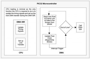
Fig. 3: PIC32 microcontroller LCC graphics flowchart
Rendering new pixels
Rendering new pixels in the frame buffer is as important as refreshing the screen. This is performed by the CPU writing to the display buffer. If the frame is stored externally, the DMA transfer is suspended while the frame is being updated. This is necessary because there is only one PMP peripheral and it is being shared by the virtual graphics controller or DMA transfer. This method does affect the refresh rate of the screen. The amount of pixel updates needs to be monitored to prevent too large a refresh rate change, otherwise the change will be perceptible by the human eye. This is done by using a pixel count variable within the virtual graphics controller that is updated on every pixel write and cleared during every DMA interrupt.
With the introduction of the EBI peripheral, the suspension time needed for a frame update is dramatically reduced. When the EBI is used for writing, less data need to be stored and restored since the PMP registers are no longer being shared for reading and writing. Also, the EBI module is a more efficient peripheral when communicating to external SRAM.
Software
The internal SRAM method uses the write strobe of the PMP for the pixel clock. Jumper rows one and two on the LCC graphics board must be set for this configuration. In this setup, all colour is 8BPP and no external SRAM is used. SRAM from inside the MCU is continuously writing its pixel values to the PMP.
For 8BPP colour, a 332 RGB colour format is used, that is three colour values for red, three for green and two for blue. This is a common colour format, because red is an easier colour for the human eye to detect than blue.
The external SRAM method uses the read strobe of the PMP for the pixel clock. Jumper rows two and three on the LCC graphics board must be set for this configuration. In this setup, all colour is 16BPP and the external SRAM contains the graphics frame that is continuously being read. For 16BPP colour, a 565 RGB format is used with five colour values for red, six for green and five for blue.
In both methods, when connecting to an LCD panel with more than 16 colour lines, the unused colour lines are tied to the most significant bits of the last colour bit being used. This ensures that a full colour scale from white to black can be achieved.
Conclusion
This article has shown how a low-cost controllerless graphics system can be implemented with microcontroller peripherals to create a virtual graphics controller using only a small amount of CPU time.


