

Post burn-in, connectors are a major point of failure of an electronic system due to mechanical and environmental stresses, and in some cases, poor design. This becomes increasingly significant as electronics, particularly robotics, permeate industrial and manufacturing applications where maximum flexibility must be combined with minimum downtime.
To meet and overcome these dual challenges, designers need to understand the function and failure modes of connectors and match the right connector to the application. Factors to be considered include environmental, functional, and mechanical stress requirements. All conditions and usage models need to be considered before making a final connector choice.
While it’s important to understand the fundamentals to ensure longevity, it’s just as important to look for and review the latest advances in connector technology to help achieve the optimum balance of performance, reliability, flexibility and cost.
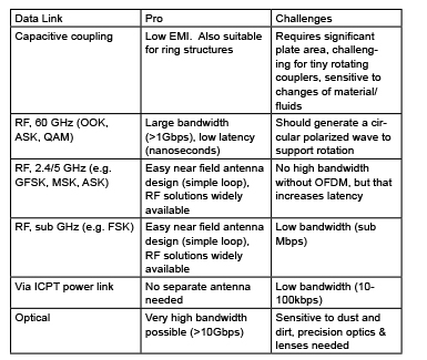
Figure 1. There are numerous options for a contactless data link, including 2.45-GHz RF, but power links are for now best achieved using inductively coupled power transfer
What exactly is a connector?
This question can be answered in two ways, functionally and structurally. Functionally, a connector provides a separable connection between two elements of an electronic system without unacceptable signal distortion or power loss. There are two important parts to this definition, the “separable connection” and the “unacceptable” performance. Both depend on the connector application and its electrical and environmental requirements.
The separable connection is the reason for using a connector in the first place, to provide easy repair, upgrading, maintenance or interconnectability. Requirements on the separable interface include mating-force limitations and meeting a specified number of mating cycles.
“Unacceptable” performance includes a large range of characteristics, but this discussion will concentrate on the limitations the connector introduces into the electronic system. The traditional approach is to use a standard, full-contact wired power and signal connector. There are many advantages and disadvantages to this approach.
-

- Figure 3. A complete contactless connectivity design integrates ICPT for power transfer and 2.45-GHz wireless for data transmission, all within an M30-type form factor. [Image courtesy of TE Connectivity]
-
- 4. Implemented in an M30-type connector, the near-field loop antenna design for a contactless connectivity-based data link is symmetrical to allow for rotation. [Image courtesy of TE Connectivity]
-
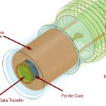
- Figure 2. In inductive coupling, the coupling is determined by the distance (z) and the ratio of D2/D, while the efficiency of power transfer between transmitting coil L1 and receiver coil L2 depends on the coupling (k) between the inductors and their Q factor
As mentioned, a separable connection provides a separate connection between two elements of an electronic system without unacceptable degradation of performance. The separable connection and unacceptable performance depend on the connector application and its electrical and environmental application. Factors to consider when choosing a connector include:
• Power distribution: Joule heating, which is proportional to the connector resistance, can result in increases in the connector operating temperature, a major factor in connector degradation. Both magnitude and stability of contact resistance are critical for power connectivity. Arcing is also significant in power applications, especially where there are hazardous gas environments.
• Signal distribution: Signal distribution requirements center around maintaining the integrity of the signal waveform. For high-data-rate systems, this may involve controlled-impedance connector designs and careful attention to signal-to-noise ratios. The magnitude of the required connector resistance is strongly dependent upon the devices in the circuitry the connector must interconnect. For many devices, high connector resistance – hundreds of milliohms – can be tolerated.
• Environmental considerations: Harsh environments, such as deep ocean or vibration sensitive surroundings, may constrain the traditional connector application and design. There may also be harsh and safety-critical applications, such as gaseous environments, which limit the application of contact technology.
• Corrosion: Corrosion occurs in many forms and can be classified by the cause of the chemical deterioration of a metal. The most common form of corrosion is rust or ferric oxide. Galvanic corrosion, or dissimilar metal corrosion, occurs when two different metals are located together in a corrosive electrolyte.
• Movement: Cabled solutions are generally constrained in their movements. Wear and tear on cables coupled to motor-driven, rotating subsystems, such as robotic arms, can lead to downtime, severely affecting productivity. A classic example is a robotic arm, which may have to move along multiple axii.
Traditionally, rotation with reliable connectivity is achieved using slip rings that are connected to stationary rings via brushes. Cables are used to position these copper rings in close proximity to enable physical contact with carbon brushes.
• Mating cycles: The connector may be designed to meet specified mating frequency and cycles from a few hundred to thousands. Cycle-life requirements affect the design and materials used in manufacturing the connector.
• Other factors: Cost, size, efficiency and the ability to transmit over certain distances may also be design criteria that need to be considered for each application.
-
- Figure 5. A contactless connectivity option implemented on a robotic arm allows 360 degrees of freedom with no brush wear typical of current slip-ring designs. Integrated sensors also enable “gentle touch” sensitivity. [Image courtesy of TE Connectivity]

-
- Figure 6: Free from the strictures of contact, contactless interconnects provide greatly improved flexibility and reliability, while magnetic coupling protects against explosions in gaseous or otherwise flammable environments.

The ability to transmit over “certain distances” as mentioned above is particularly interesting. There are instances where power and data need to be transferred wirelessly across small distances, such as through a wall or other material. Also, more connector freedom may be needed without mechanical wear and tear, or the environment may be too hazardous to introduce any possibility of arcing.
It’s at this point that advances in contactless connectivity need to be considered.
Contactless connectivity
“Contactless connectivity requires both contactless power and contactless data technology which can easily connect over a short distance without physical contact” [TE Connectivity (TE)].
There are many benefits to be accrued from contactless over traditional connectors which should be considered when deciding how to meet the design specification most effectively. These include:
• Improved reliability: Delivers robust power and data without wires or physical contact. Also, the connectors are hermetically sealed ensuring environmental integrity.
• Greater flexibility: There is an unlimited range of motion, allowing 360° movement, tilt, angle and misalignment.
• Unlimited mating cycles: There are unlimited mating cycles in wet and dusty environments. This is particularly suitable where slip rings or spring cables reach their limit.
• Connection through walls or materials: Contactless technology allows connection through walls or materials, which is not possible with traditional connectors.
• Improved safety: There is no arcing, which is a major plus in hazardous environments such as gas-filled chambers.
• Cost savings: There is no wear and tear thus improving the uptime and reducing maintenance.
However, a truly contactless connector must be able to transmit both data and power. For power, there are few options. Capacitive power transfer (CPT) has the advantage of being able to penetrate (floating) metal and has low EMI, but it suffers from low power density and short range. Some generalized comparisons of various wireless options, using pros and cons, are shown for easy reference (Figure 1.)
For contactless power transfer, an inductively coupled power transfer (ICPT) option proves to have more pros than cons. It is has high power density at reasonable distance, is well known with widely available product and technology solutions, and high efficiency is possible. The downside is that it cannot penetrate metal.
For data transmission, there are a number of options. Capacitive coupling’s low EMI is also an advantage for data transfer, but such coupling requires significant surface-plate area, which can be challenging for tiny, rotating couplers. Inductive coupling for data suffers from low bit rates. Other options include RF at 60 GHz, 2.45 or 5 GHz, sub-GHz, and ICPT, as well as optical links. Each has pros and cons, as shown in Figure 1.
The 2.45-GHz industrial, scientific, medical (ISM) band is also unlicensed, with global acceptance and wide usage, most notably as “wireless Ethernet” under the moniker of Wi-Fi.
In the final analysis, it turns out that a hybrid architecture, RF for data and inductive coupling for power, is the best approach for contactless connectivity.
Defining induction
Inductive power transfer has been with us for quite some time, but for the sake of clarity a quick run through of how it works is useful in understanding its utility as a wireless power-transfer mechanism.
Faraday’s law of induction states that the induced electromotive force in any closed circuit is equal to the rate of change of the magnetic flux enclosed by the circuit, or mathematically as:
Where is the electromotive force (EMF) and ΦB is the magnetic flux.
The basic principle of an inductively coupled power-transfer system is shown (Figure 2). It consists of a transmitter coil L1 and a receiver coil L2. Both coils form a system of magnetically coupled inductors. An alternating current in the transmitter coil generates a magnetic field, which induces a voltage in the receiver coil. The efficiency of the power transfer depends on the coupling (k) between the inductors and their quality, defined as their Q factor.
The coupling is determined by the distance between the inductors (z) and the ratio of D2/D. The shape of the coils and the angle between them further determines the effective coupling.
The performance of a wireless power link can be improved using resonant inductive coupling. Resonance of a circuit involving capacitors and inductors occurs because the collapsing magnetic field of the inductor generates an electric current in its windings that charges the capacitor, and then the discharging capacitor provides an electric current that builds the magnetic field in the inductor. This process is repeated continually.
At resonance, the series impedance of the two elements is at a minimum and the parallel impedance is at maximum. Resonance is used for tuning and filtering, because it occurs at a particular frequency for given values of inductance and capacitance.
To cancel the influence of the inductive reactance and the capacitive reactance they should have equal magnitude, ωL = 1/ωC, so:
Where L is the inductance in Henrys, C is the capacitance in Farads , and ω = 2πf, in which f is the resonance frequency in Hertz. In low-power systems and for high power efficiency, higher k and Q are required.
Applications of inductive coupling
Taking inductive coupling a step further, the idea of using it to transmit power wirelessly has been around since the mid 19th century. Nikola Tesla initially experimented successfully with the lighting of gas-discharge lamps wirelessly over a distance of approximately 15 feet. This sparked interest in wireless power transfer technology and applications involving microwaves, lasers, and solar cells capable of transmitting power from space.
Closer to home, modern power mats used to charge mobile devices use resonant inductive coupling, but use a “handshake” between the charging surface and the device, and then energy is transferred to the device. It is an intelligent system and will only send power to identified devices and only at a rate determined by the charging profile of the device’s battery.
Inductive power transfer is also the operating principle behind passive RFID tags, toothbrushes, and contactless smart cards.
Integrating wireless power and data
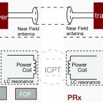
The principle challenges with a contactless connector are integrating the power coils and near-field antenna into a very small form factor that is relatively easy to manufacture. This requires knowledge of mechanical design and power electronics, as well as magnetics, RF circuit design and antennas.
The power-transmit portion takes the 24-V DC supply, puts it through a circuit protection section, followed by a DC-DC converter and a DC-AC converter. The converter output feeds the transmit primary coil, which has a capacitor in parallel as part of a resonant tank that allows it handle variable loads and distance. The receiver side also contains a resonant tank. The received power is rectified, put through a DC-DC converter to deliver 24 V DC to the point of load.
The inductive power link itself has an efficiency of approximately 95%, while the output power is always 12 W. The overall system efficiency depends on the data link and includes the losses on the board, e.g. through the DC-DC conversion.
Using this circuit and techniques, an M30-diameter implementation can provide 12 Watts of output power. The effective power over distance is 7 mm (Z) distance for M30. In addition, the coupling is tolerant of misalignment up to 5 mm.
For contactless data transmission, the data is sent separately through a signal converter to a 2.45-GHz transceiver and out to a near-field antenna (Figure 3). On the receive side, the process is reversed.
The first variant is designed for sensor applications and supports up to eight PNP channels, unidirectionally from receiver to transmitter, with a switching frequency of 500 Hz (maximum). Development of higher data rates is on going, with a goal of supporting industrial Ethernet at 100 Mbits/s.
The data connection happens upon physical connection, and is by necessity dynamic, occurring without user interaction. The range is short, up to a couple of millimeters, which is good for security and RF emissions purposes. The connector can accommodate up to eight digital PNP channels, with the current variant.
To enhance reliability, the data link uses redundancy in the 2.4-GHz channel, has minimal far-field interference and the antenna design is symmetrical to allow for rotation (Figure 4). It’s also tolerant of misalignment, rotation and tilt.
The full system efficiency, meaning the efficiency of the power and data link together, is ~ >75% (output power of receiver end/input power to the transmitter). Of course, this depends on the load, the distance and other factors, but it also includes the losses through the data link and PC-board assemblies.
In rugged or dangerous environments, connectors are hermetically sealed to IP67, even if they are not connected with each other.
Unleash the robots
The challenge of integrating contactless data and power translates to relatively high cost, so the target applications are those where the capabilities of classic connectors have reached their limit in terms of mating cycles or environmental conditions, or where the application requires complex harness construction, and especially for new applications, such as connecting through walls and materials, or connections on the fly.
One such application is robotic systems, which are being increasingly adapted to manufacturing and production processes that require greater complexity and precision. Given the rigors of the environment and the cost of downtime, maximizing reliability through dependable connectivity can pay dividends in the long term.
In a typical robotic application, cables limit the range of motion and the constant movement and friction of the mechanical parts also creates wear and tear. Robots also need to move rotationally to perform complex tasks. Traditionally, rotation is enabled with rotating connectors, spring cables, or slip rings, the latter of which are mechanically connected to stationary rings via brushes. Cables are used to position these copper rings in close proximity to enable physical contact with the carbon or metal brushes. The brushes then transfer the electrical current to the ring, creating rotation.
This constant friction creates wear and tear on the moving contacts, slip rings and brushes, which must be replaced frequently. This results in increased downtime and reduced productivity.
With contactless connectors, the deterioration of moving components is no longer a limiting factor (Figure 5.)
Issues typically affecting connectivity in harsh environments, such as water, dust or vibrations, no longer impact the reliable delivery of power, data and signals. Contactless connectivity can replace complex and expensive harness constructions and slip rings, enabling connectivity where you could not connect before. The ability to integrate sensors within the robotic graspers or “fingertips” for force feedback to the system also enables “gentle touch” sensitivity for delicate items.
Data to date shows that the total cost of ownership (TCO) using contactless connectors versus traditional solutions is positive within the first few months through increased efficiency, reduced downtime, maintenance savings and increased output.
It may be the case that contactless connectivity will provide designers with an entirely new way of thinking about mechanically designed machines.
References:
Connector Design/Materials and Connector Reliability
Robert S Mroczkowski
https://en.wikipedia.org/?title=Electromagnetic_induction
Engineersgarage.com
Wireless Power Transfer Using Resonant Inductive Coupling
Sangwook Han, and David D. Wentzloff Electrical Engineering and Computer Science Department The University of Michigan, Ann Arbor
My Inventions: Nikola Tesla’s Autobiography
Nikola Tesla
TE Connectivity
*Definition and Benefits of Contactless Connectivity
For factory and industrial environments where dust, liquids, and gases combine with friction, power and robotic system wear and tear through multiple axii of rotation, designers need a new approach to connectivity. This new approach needs to be able to overcome these many environmental and operational challenges to secure, reliable, flexible, and robust connectivity – for both power and data.
The solution lies in a new interconnection system, based on both contactless power and contactless data technology, which can easily connect (and disconnect) over a short distance without using any mechanical contact, demonstrated in the ARISO connectors from TE Connectivity.
To date, contactless, or wireless, data has come in many forms, from cellular to Wi-Fi, Bluetooth and ZigBee; however, for low-data-rate sensor data, these interfaces have a lot of packet-processing and network-interface and mesh networking overhead. This costs the designer, both in terms of real estate and power consumption, as well as direct component costs.
For its part, wireless power has undergone a revolution of late, thanks to the efforts of groups such as the Wireless Power Consortium, pushing Qi, as well as the now merged Alliance For Wireless Power and Power Matters Alliance. These have developed standards for the transmission of power levels of up to 5 W, with a usable range of up to 30 mm, to charge mobile devices, particularly handsets. The standards use variations of inductive and resonant power at various frequencies to achieve this, but all require a relatively large footprint, while also being relatively costly.
The trick is to find the sweet spot in terms of data rates, cost and power consumption for wireless data, and in terms of range and cost for wireless power, such that both interfaces can fit within the confines of a typical M30- or M12-type sensor head.
Thanks to the work that been done to date in terms of RF function integration to lower cost, as well as increases in the efficiency of wireless power transmission, this sweet spot is attainable by matching the wireless data and power transmission circuits to the application’s low power and short range requirements.
For data, the 2.45-GHz unlicensed band was chosen as it can be implemented using a near-field antenna design with a simple loop
For power, the principle challenges are integrating the power coils and near-field antenna into a very small form factor that is relatively easy to manufacture. This requires knowledge of mechanical design and power electronics, as well as magnetics, RF circuit design and antennas.
With both the data and power transmission now integrated into a single connector head, the options and application dynamics change, dramatically. Flexibility jumps to a higher level, with 360° rotation without cable, connector, or harness wear and tear. This freedom of movement also allows for connector tilt, angle or misalignment, while the rotational freedom enables faster maintenance-free rotation as well as faster return to starting points, as the rotating heads don’t have to rotate back through 180° offset, but instead can keep going to 360°.
Contactless connectors are vibration resistant and are hermetically sealed against harsh environments and have unlimited mating cycles, despite wet & dusty environments. The magnetic coupling is particularly attractive in gaseous applications or where flammable liquids or material are present.
Other advantages include easy on-the-fly connection without the traditional mechanical limitations, design flexibility and cost savings by enabling the transfer of power and signal through fluids and walls, as well as improved reliability for reduced maintenance & lower total cost of ownership.
For more information about the ARSIO range of products from TE, visit the company’s site.
ARISO and TE Connectivity are trademarks.


