Abstract – The radio-frequency (RF) detection coil is a transducer device that excites the nuclear magnetic resonance (NMR) signal and then detects it in the magnetic resonance spectroscopy (MRS) measurement. The signal-to-noise (SNR), spatial and temporal resolution, spatial uniformity, and the efficiency with which RF excitation power is used and lost to the measurement sample are all dependent on the RF coil’s performance. The success of the MRS measurement is largely determined by the proper choice and application of the RF detection coil. There are many coil design choices available and we need to fit the best options for the specific application. Among coil design choices there are transmission line coils, wire coils (surface coils, volume coils), TEM coils. The types of surface coils are single loop solenoids, multiple-loop arrays, and the types of volume coils solenoids, crossed pairs, saddle pairs, phased arrays, cage coils, Litz coils. TEM coils are coaxial lines, strip lines, and microstrips. TEM coils can be capacitively shortened and tuned; half-wave trans-mission line resonators are similar to the slotted tube resonator but with a number of practical features that lend themselves to modern utility. Typical features are where the center conductor ‘rungs’ of these coils generate a highly uniform field like rungs of a birdcage. The TEM coil can be double-tuned by tuning alternating rungs to alternating Larmor frequencies of the desired nuclei. The Larmor or precessional frequency in MRI refers to the rate of precession of the magnetic moment of the proton around the external magnetic field.
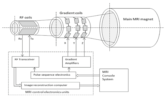
The radio-frequency (RF) detection coil is a transducer device that excites the nuclear magnetic resonance (NMR) signal and then detects it in the magnetic resonance spectroscopy (MRS) measurement. The signal-to-noise (SNR), spatial and temporal resolution, spatial uniformity, and the efficiency with which RF excitation power is used and lost to the measurement sample are all dependent on the RF coil’s performance. The success of the MRS measurement is largely determined by the proper choice and application of the RF detection coil. There are many coil design choices available and we need to fit the best options for the specific applications. Among coil design choices there are transmission line coils, wire coils (surface coils, volume coils), TEM coils. The types of surface coils are single loop solenoids, multiple-loop arrays, and the types of volume coils solenoids, crossed pairs, saddle pairs, phased arrays, cage coils, Litz coils. A saddle coil system can be constructed by crushing two equal rectangular coils on a cylindrical shell. The same current is carried by each coil, and the direction of the flowing current may be set in Helmholtz or anti-Helmholtz configuration. The magnetic flux field (“magnetic field”) is generated by a saddle coil system and is inspected in the whole space in two different spatial planes. The uniformity of the magnetic field is analysed by using Taylor series and the optimum geometry can be obtained from second-order Taylor expansions. The saddle coil geometric parameters are optimised for best performance. The deviations of the magnetic field which is produced by an optimum-compensating saddle coil system are constructed with typical NMR field-cycling magnetic field in homogeneities. The basic components of any MRI system: The main magnet produces the B0 field, necessary to align the spins and achieve equilibrium. Gradient coils enable image encoding in the x, y, and z direction (frequency, phase, and slice-encoding directions, etc.). The RF coil is the part of the MRI system that excites the aligned spins and receives an RF signal back from the sample. All the components are controlled and interfaced with the user via a console (Fig. 1).
Fig. 1 MRI scanner system (main MRI magnet, gradient coils, RF coils, control units and console system)
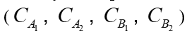
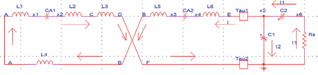
In the case that RF Rx coil is saddle coil the signal acquired using Rx coil is MR (Magneto resonance) signal that carries information about the imaging object in the magnetization form. We analyse dual frequency actively decoupled saddle coil. The actively decoupled saddle coil is made from copper wire (volume coil). There are four fixed value capacitors
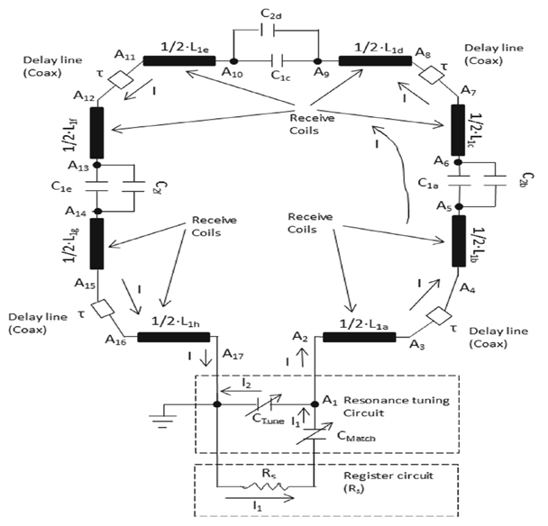
The two coax cables which connect the tuning capacitors (C1, C2) to our half saddle coil (branch A) are represented by two delay lines ,
Fig. 3 Half saddle coil (branch A), coax cables, and tuning networks and register system equivalent circuit
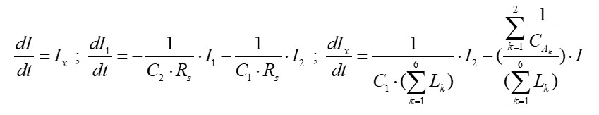
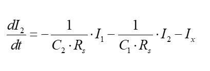
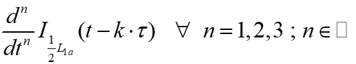
Assumption: The derivatives of
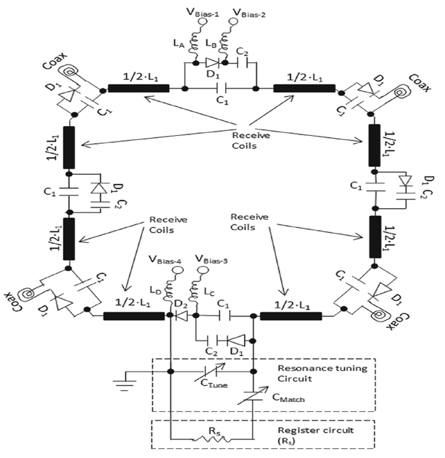
Magneto Resonance (MR) of nuclei other than hydrogen is investigated. MRI uses the movement of protons within a magnetic field to generate an image. Within the constant magnetic field of an MRI scanner, tissues that contain free hydrogen nuclei (protons) generate varying signals when pulses of radiofrequency (RF) energy are applied to them. The common scheme of using trap circuits for dual-tuned operation results in increased coil losses as well as problems in obtaining optimal tuning and matching at both frequencies. By using PIN diodes, we switch the coil between two resonance frequencies. The dual-tuned coil design utilized PIN diodes to switch between different capacitance values for setting two difference resonance frequencies (Fig. 4).
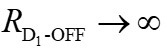
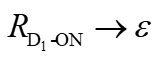
The switching between lower resonance frequency and higher resonance frequency of the dual—tuned coil is done by switching ON and OFF PIN diodes D1. We consider that the PIN diodes (D1) are ideal; when diodes D1 are in OFF state then have very high resistance
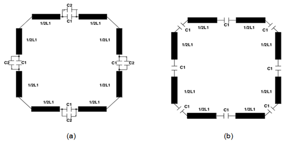
Fig. 5a/b Dual-tuned coil with PIN diode switching’s equivalent circuit (a) lower resonance frequency, (b)
higher resonance frequency.
The switching of D1 diodes is done by bias voltages
Fig. 6 Dual-tuned coil circuit for lower resonance frequency circuit (D1 diodes are ON state (short) and D2 is at OFF state (disconnected)) is presented
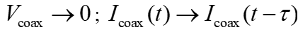
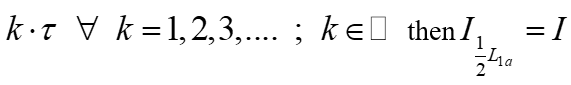
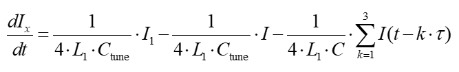
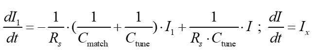
We get the set of DDEs (Delay differential equations) for dual tuned coil system where D2 is at OFF state and D1 diodes are ON state (lower resonance frequency case). We consider the coax transmission lines are functioned as short conductor then dual resonance frequency coil’s corner capacitors are shorted
We consider the derivations of
Reference
Secure Development Processes Advance CRA Readiness and Increase Customer Cybersecurity Assurance CHANDLER, Ariz., April 2,…
There is a lot of "SaaS is dead" or "AI is coming for your job"…
Tessenderlo-Ham, Belgium, 31 March 2026 – Melexis announces the MLX80339, a code-free three-phase fan driver…
Voltify, the startup pioneering a new approach to rail electrification, today announced it has raised…
Siemens has signed a letter of intent with the European Space Agency to join its…
IDS Imaging Development Systems has introduced the Nion, a new industrial Time of Flight (ToF)…