Abstract
This article provides the methodology to calibrate digital-to-analog converters (DACs) specifically for pin electronic drivers, comparators, load, PMU, and DPS. DACs have nonlinear properties such as differential nonlinearity (DNL) and integral nonlinearity (INL), which can be minimized with the use of gain and offset adjustments. This article describes how to make those corrections for improved level-setting performance.
Introduction
Automated test equipment (ATE) describes testing apparatuses designed to perform a single or sequence of tests on one device or multiple devices at a time. Different types of ATE tests electronics, hardware, and semiconductor devices. Timing devices, DACs, ADCs, multiplexers, relays, and switches are the supporting blocks in the tester or ATE system. These pin electronic devices can deliver signals and power with precise voltages and currents. These precision signals are configured by the level-setting DACs. In the ATE portfolio, some pin electronic devices have calibration registers, and some calibration settings are stored off-chip. This article describes the DACs’ function, errors, and calibration via gain and offset adjustments.
Digital-to-Analog Converter (DAC)
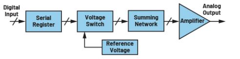
A DAC is a type of data converter that converts digital inputs to corresponding analog output levels. An N-bit DAC can support 2N output levels. A higher number of bits corresponds to a higher DAC output resolution.
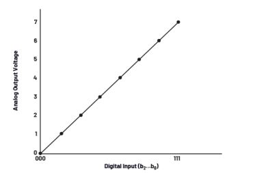
First, the N-bit digital input is provided to a DAC serial register. The voltage switch and resistor summing network converts the digital inputs to analog output levels. The transfer characteristics of the DAC plot are shown in Figure 2. For a 3-bit DAC, 23 digital input yields eight analog output levels.
DAC Errors
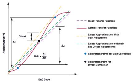
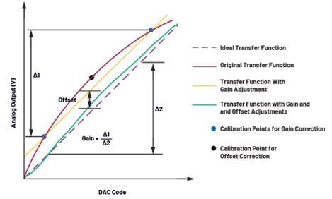
In the real world, converters are not ideal. Because of the variance in resistance values, interpolation, and sampling, the DAC transfer function will not be a straight line, or linear. These errors are namely referred to as differential nonlinearity (DNL) and integral nonlinearity (INL). DNL is the maximum deviation of the output levels from ideal step sizes. It is derived from the difference between two successive output voltage levels. INL is the maximum deviation of the input/output characteristic from the ideal transfer function. With the gain and offset corrections, the INL errors can be reduced.
The INL in Figure 3 shows the deviation between actual transfer function and ideal transfer function. The gain error of the DAC indicates how well the slope of the linear approximation of the actual transfer function matches the slope of the ideal transfer function. Adjusting the gain will affect the angle of the linear approximation when graphed. The offset error is the difference between the measured value and chosen desired zero-offset point. Adjusting the offset will shift the entire linear approximation up or down accordingly. The INL of a single code is the sum of both gain error and offset error at any given point. After calibration, the transfer function can be a line drawn between end points once the gain and offset errors have been minimized.
Calibration Routine
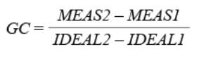
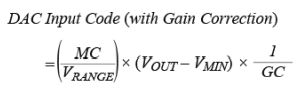
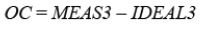
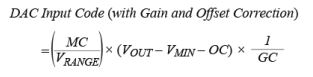
The user can establish a calibration routine to reduce DAC nonlinearities using gain and offset corrections. The following procedure explains the step-by-step process of an example calibration routine.
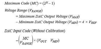
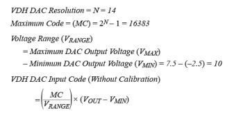
For an N-bit DAC:
The desired zero-offset point varies by application. The user should define the best value based on their application. Some users may prefer to use zero volts to get an exact ground reference point. Some users prefer to use the midpoint of their operating range to minimize the overall INL error.
Example 1
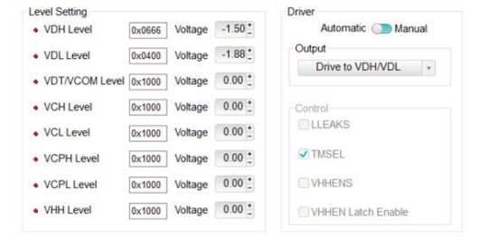
Consider the MAX32007, an octal DCL with integrated level-setting DACs and PMU switches. The MAX32007 has internal DACs for level-setting VDH, VDL, VDT/VCOM, VCH, VCL, VCPH, and VCPL. These DACs do not have internal calibration registers. To calibrate the DACs, follow this procedure:
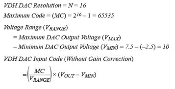
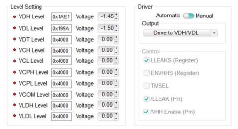
Apply the DAC voltage levels and driver settings as shown in Figure 4. Note that the lowest operating VDH DAC value is –1.5 V, the highest operating value is 4.5 V; in this case, the zero-offset point value is 1.5 V.
Example 2
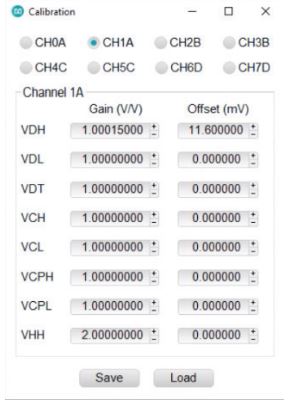
Consider the MAX9979, a dual DCL with integrated level-setting DACs and PMU. The MAX9979 has internal DACs for level-setting VDH, VDL, VDT, VCH, VCL, VCPH, VCPL, VCOM, VLDH, VLDL, VIN, VIOS, CLAMPHI/VHH, and CLAMPLO. These DACs have
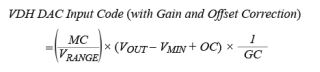
internal calibration registers. In Example 1, the DAC input codes are adjusted to minimize the INL error. In Example 2, the DAC input code remains the same and the calibration registers adjust the output stage buffer to minimize the INL errors, as depicted in Figure 6. To calibrate the DACs, use the following procedure:
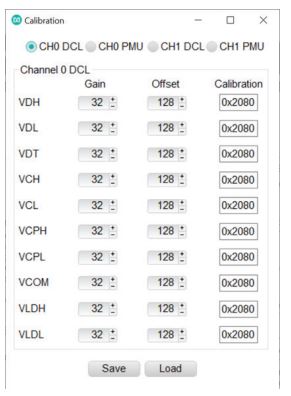
Note: gain and offset corrections can be applied on Menu à Options à Change à Calibration, as shown in Figure 8. Conversion of gain and offset corrections to gain and offset codes are given in the MAX9979 data sheet.
About the Author
Minhaaz Shaik is a member of the technical staff at Analog Devices with more than five years of experience as an applications/ systems engineer in the analog and mixed-signal domain. Minhaaz mainly focuses on product lines such as automated test equipment (ATE) pin electronics, ADCs, DACs, and supervisory and interface ICs. She is a highly skilled professional in electronic system design, lab evaluation, automation, customer support, and technical writing, and has significant knowledge in SPICE simulations and circuit design. She can be reached at minhaaz.shaik@analog.com.
This acquisition further establishes Quantum Machines as the quantum company with the broadest global footprint,…
Supporting planned growth in InP silicon photonics technology Resolving all prior IP disputes between the…
Norwest leads the round with strategic participation from Snowflake Ventures, as Jedify addresses the AI…
Round brings total funding to $15 million from U.S., European and Israeli investors to support…
Quantum Machines achieves 99.5% median two-qubit gate fidelity when operating Rigetti Computing’s Novera™ superconducting QPU…
Unframe, the managed AI delivery platform for global enterprises, today announced it has crossed $100…