
Everyone knows that if you dissipate heat inside a confined space then the temperature in that space will increase i.e. the ambient temperature inside the enclosure will rise.
If you have an enclosure containing a power supply and its load i.e. the PCBs that its powering then as the ambient air temperature increases due to the heat dissipated by both, the power supply and the PCBs will further heat up, possibly beyond their maximum operating temperatures.
This is a bad situation as heat is the number one cause of unreliability or reduced lifetime within an electronic system due to the life time of electrolytic capacitors being strongly linked to their operating case temperature.
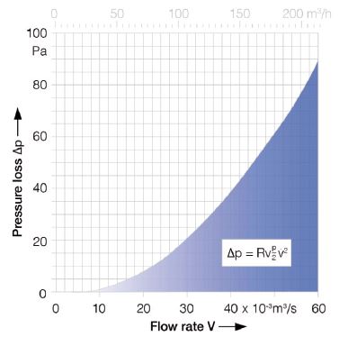
Figure 1 – Characteristic
device curve
Other components are also less reliable the hotter they become and with the trend of making power supplies smaller with less heat-sinking then they must be carefully thermally managed.
An easy way to do this is to use a fan to remove excess heat from the enclosure.
Some power supplies are designed to be forced cooled by use of a system fan. In these cases, the air flow required for adequate cooling will be specified in the power supply data sheet. It is important to bear in mind that this is the air flow needed at the power supply itself and not at some point even a short distance away. As air will always follow the path of least resistance, only a portion of the air pushed by the fan will actually reach the power supply where it is needed. Internal baffles will help to direct air along the required path to reach and cool the target components.
For the cases where the power supply is perhaps a convection cooled design, or where the equipment just needs to run at a lower temperature, the air flow needs to be calculated using the steps below.
Firstly it is required to establish the maximum operating temperature that either the power supply or the electronics could safely operate in. For the power supply itself this may typically be 50 °C which may be related to the safety approvals or a lower value to increase the lifetime. As a general rule of thumb, a reduction of an electrolytic capacitor case temperature of 10 °C results in a doubling of its lifetime.
We then need to consider the highest air temperature surrounding the equipment enclosure containing the power supply and the difference between the two is the maximum allowable temperature rise. As an example, if the power supply is able to operate at an ambient of 50 °C, and if the equipment containing the power supply is intended to be operated in a non-air conditioned
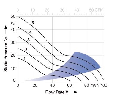
Figure 2 – Fan flow rates at
different air pressures
environment where the maximum temperature could reach as high as 40 °C, then the allowable temperature rise is 10 °C.
The next step is to establish the amount of power to be dissipated. The total power dissipated inside the enclosure is the sum of the power used by the load plus the power lost by the power supply as waste heat. As an example, if the load taken by the electronics is normally 260 W and assuming that the power supply is 80% efficient then the total heat dissipated is 260 W / 0.8 i.e. 325 W. Establishing the volume of airflow required can then be calculated. There is a simple universal formula for working out how much airflow is required to maintain a particular temperature rise for a given amount of heat which uses a constant of 2.6.
Unfortunately, finding a solution is not as straight forward as working out the required airflow as in the above solution and using the result to select a fan with the corresponding rating as fan air flow figures are given for use in free air but in reality an enclosure will have a natural resistance to air flow known as pressure drop or loss which will detract from the fan’s free air performance.
The pressure loss will be different for every application due to PCB sizes and locations, size of inlet and outlet vents, cross sectional area within the enclosure that the air flows throughetc. Where things get a little tricky is that the pressure loss also depends on the speed of the air as it passes through the enclosure and that pressure loss in turn is affected by air speed. A faster air speed will result in a higher pressure loss, but a higher pressure loss will reduce the air speed. If careful fan selection is not done, then the fan could become useless in an application where the resulting pressure loss and air speed reach an equilibrium point that is below the required level to remove the heat from the enclosure.
It would be too complex to determine the actual pressure loss for every application as it would require detailed knowledge of fluid dynamic equations but it can be approximated by using the characteristic device curve shown below in Figure 1. This will give an initial starting point which can be used for further evaluation.
If we consider the air flow calculated previously, the curve indicates that the pressure loss would be 11Pa. We then know that a fan able to generate an air flow of 84.5m3/hr into a pressure loss of 11Pa is required. Each fan manufacturer will publish a graph for every fan indicating the air flow at differing pressure losses. In the example below, Figure 2, curves are given for 5 fans. The light coloured cone shows the optimum operating range for each of the 5 fans. In our example, fan 5 would need to be used to ensure the required air flow of 84.5m3/hr with a pressure drop of 11Pa.
Once the pressure drop and air flow required have been established, there are a few other considerations to think of.
As previously stated, for general equipment cooling, the fan can be located anywhere as long as the air flows amongst the heat
source components. However, for a power supply that is designed to be forced cooled, the amount of air flowing over the
power supply is critical for correct and reliable operation. If the fan cannot be located right at the power supply, or if the entire air flow cannot be directed over the power supply then the fan chosen will need to have a very much larger rating. Some fans are specified with an air speed in linear feet per minute (LFM). Others have a volumetric rating in cubic feet per minute (CFM) or cubic meters per hour (m3/hr). To convert between the two, the cross sectional area of the fan venturi needs to be known.
For a forced cooled power supply, the required air flow may be given in either a speed rating such as LFM or a volumetric rating such as CFM. The only reliable way to convert between the two is to use the cross sectional area of the power supply.
Equipment with fans will often have dust filters to prevent unwanted dust entering into the equipment. A filter will add to the resistance of air flow contributing to the pressure loss and will need to be taken into consideration but more importantly, as the filter clogs with dirt, the pressure loss may get significantly higher and a fan with suitable rating at the beginning of operation may become the wrong choice after a period of use. For this reason, dust filters should be regularly cleaned or replaced.
Adding a fan to a piece of equipment makes it audible noisy. Some applications cannot tolerate any noise for example in some hospital applications, recording studio applications etc. Even in applications going into a noisier environment, it is usually desirable to minimise audible noise. This can be done by several methods. Firstly, using a fan with a higher quality bearing. Ball bearing fans are generally quieter than sleeve bearing fans and have the advantage of a longer lifetime. Of course, there are fans that use impregnated oil within sleeve bearings which may negate this.
Also, for a given air volume, a larger fan is generally more quiet than a smaller fan due to the slower blade speed required.
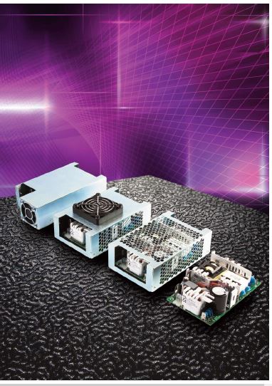
Figure 3 – GCS250 from XP
Power requires just 7 CFM of
air flow
Consideration should also be given to any noise generated by fan blades passing by a nearby fixed part of the fan such as a fan strut or a finger guard. If a finger guard can be separated even slightly from the fan blades, then the noise may be reduced.
Another method to mimise noise is to reduce the fan supply voltage. Fans are specified with an operating voltage range and those with a DC input usually spin at a speed dependant upon the actual DC voltage supplied. The slower spinning fan will emit less audible noise.
As the thermal management of modern power supplies is becoming increasingly important due to smaller heat sinks volumes and higher power densities, data sheets now contain information essential for equipment designers to ensure that the power suppliers are not operated at too high a temperature in the form of specific maximum temperatures for a selection of components. Once the fan has been chosen using the proceeding method, a final check should be done by measuring these
component temperatures in the final configuration. If it looks like the component temperature will exceed the value indicated in the data sheet then the air flow and direction should be re-assessed An example of an air cooling power supply is the GCS250 from XP Power. It requires just 7 CFM forced air flow. Compared to many in the industry, some of which need up to 30 CFM, the lower air flow requirements of the GCS250 help keep audible
noise to a minimum


